Structural element and method for producing a structural element

a technology of structural elements and manufacturing methods, applied in the field of structural elements, can solve problems such as inferior heat conduction, and achieve the effect of efficient and economical manufactur

Active Publication Date: 2015-02-05
GROZ BECKERT KG
View PDF13 Cites 1 Cited by
  • Summary
  • Abstract
  • Description
  • Claims
  • Application Information

AI Technical Summary

Benefits of technology

[0008]It is an object of the invention to provide an improved structural element that can be used in connection with high static loads, yet lends itself to efficient and economical manufacture.
[0010]A supporting shell with a second concrete layer is provided at a distance to the facing shell. A supporting shell reinforcement is located in this second concrete layer. In one embodiment, the supporting shell reinforcement can consist of a different material than the textile reinforcement of the facing shell. In particular, the supporting shell reinforcement may be made of metal, for example of steel. In the alternative, provision can be made for textile material, for example a knit, plait, woven fabric or nonwoven fabric, for the supporting shell reinforcement. The static load of the structural element is accommodated and supported by the supporting shell. Typically, the facing shell, which is spaced apart from the supporting shell, serves to accommodate small loads and in particular to improve the optical impression of the structural element as well as for weather protection. For example, it covers an insulating layer, which is arranged between the supporting shell and facing shell. Due to the flat and light textile reinforcement in the facing shell, the latter can be embodied so as to be particularly thin and therefore particularly light.
[0011]Separate connecting bodies are arranged between the textile reinforcement and the supporting shell reinforcement. The connecting bodies have a rigid three-dimensional form and are formed by means of a three-dimensional textile grid structure, which is in particular free from metallic elements. The connecting bodies are thus not designed as massive closed bodies, but as grid bodies with a plurality of through holes or meshes, respectively. The connecting bodies are thus very light. They have an inferior heat conduction and thus do not form thermal bridges between the facing shell and the supporting shell. In addition, such connecting bodies of a three-dimensional textile grid structure can be produced easily and can be handled equally easily in response to the production of the structural element. For example, the three-dimensional textile grid structure can be produced by angling and / or bending of a textile grid, which extends in a planar manner in a plane and by fixing the curved and / or angled textile grid in the desired shape. The textile grid can thereby be brought into the desired three-dimensional shape and can be fixed, for example by means of heat impact and / or by means of a coating, for example with a resin. Due to the grid structure, the connecting body connects very well to the two concrete layers. To provide the desired position of the connecting body prior to pouring the concrete layers, said connecting body can be connected very easily to the textile reinforcement due to its grid structure, for example by means of tie wire or cable ties by way of the textile grid structure can encompass glass and / or carbon fibers.
[0012]Preferably, each connecting body encompasses a constant cross sectional contour in its direction of extension. The connecting body can thus be produced as longitudinal element and can be cut off easily in the required length for the structural element. In the alternative, it is also possible to initially trim a flat textile grid in the desired length and to subsequently produce the three-dimensional textile grid structure therefrom and thus the connecting body by bending and / or angling and fixing in the desired shape.
[0013]In the case of a preferred embodiment, each connecting body has at least two grid sections, which extend in different spatial planes. In particular, two adjacent grid sections are aligned at a right angle to one another. In one embodiment, each connecting body has a first grid section as well as a second grid section, which are arranged parallel to one another and at a distance. A third grid section is oriented at a right angle to the first and to the second grid section and connects the first grid section to the second grid section. Preferably, a connecting body comprising a U-shaped cross section is created in this manner. In this embodiment, the first and the second grid section extend in a respective concrete layer, whereas the third grid section bridges the distance between the two concrete layers. In its extension plane, the third grid section can support the forces which are introduced into the facing shell very well and can transfer them into the supporting shell.

Problems solved by technology

They have an inferior heat conduction and thus do not form thermal bridges between the facing shell and the supporting shell.

Method used


Image

  • Structural element and method for producing a structural element
  • Structural element and method for producing a structural element
  • Structural element and method for producing a structural element

Examples


Embodiment Construction

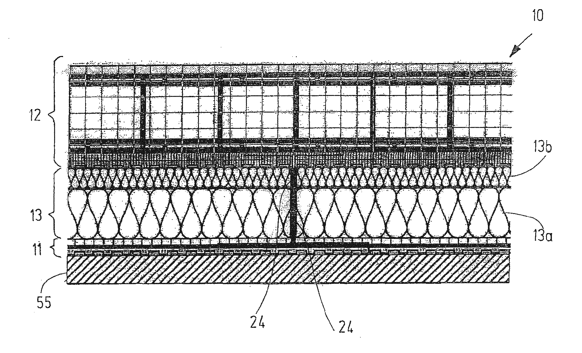
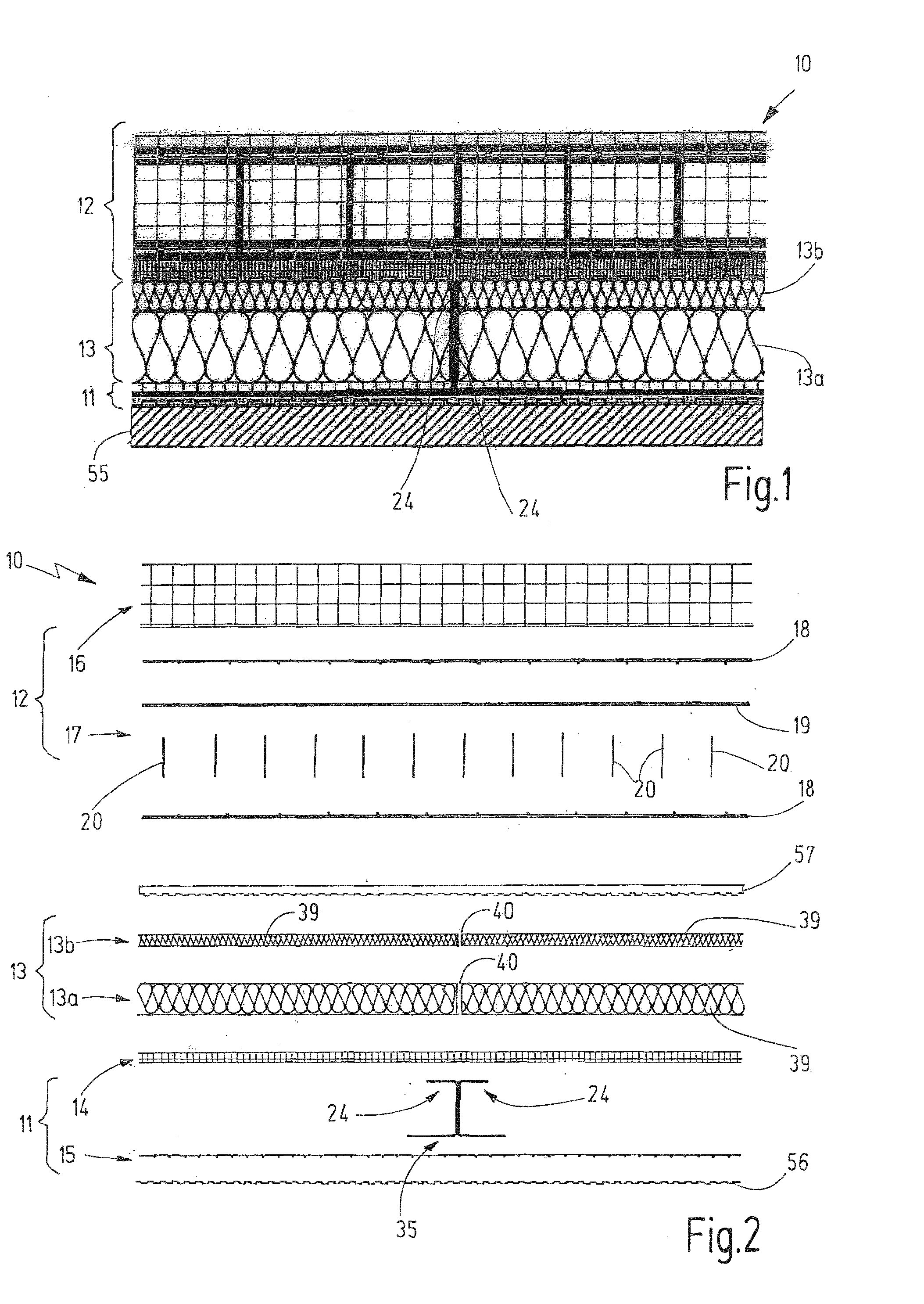
[0026]Referring now more particularly to FIGS. 1 and 2 of the drawings, there is shown in illustrative structural element 10 in accordance with the invention. The structural element 10 has a facing shell 11, a supporting shell 12, and an insulating layer 13 arranged between the facing shell and the supporting shell. The insulating layer 13 can be formed by a plurality of insulating layers with the same or different thickness. As required, the insulating layers can consist of a different material. In the exemplary embodiment, provision is made for a first insulating layer 13a and for a second insulating layer 13b which preferably rest directly against one another. The stacks of the insulating layers 13a, 13b can be offset to one another. Connecting bodies 24 are arranged in position and / or are spaced apart from one another such that common insulating board measurements can be used. If the insulating layer 13 consists only of a single insulating layer, the stack is formed by means of ...


PUM

PropertyMeasurementUnit
thicknessaaaaaaaaaa
thicknessaaaaaaaaaa
thicknessaaaaaaaaaa

Abstract

A structural element (10) for use as a ceiling element or wall element. The structural element (10) has a facing shell (11) and a relatively thicker supporting shell (12). The facing shell (11) has a first concrete layer (14) with a textile reinforcement (15) arranged therein. The supporting shell (12) has a second concrete layer (16) and a supporting shell reinforcement (17) in the form of a box-grid structure from interconnected structural steel elements (18, 19, 20). The facing shell (11) is connected to the supporting shell (12) by a plurality of metal-free connecting bodies (24)in the form of a three-dimensional a textile grid structure (25). The textile grid structure can be produced as a woven fabric, a plait, a nonwoven fabric or a knit from carbon fibres and / or glass fibre threads that have a coating to produce the three-dimensional structure. Each connecting body (24) extends in at least two spatial planes.

Description

FIELD OF THE INVENTION[0001]The present invention relates generally to structural elements and a method of production, and particularly to structural elements that can be used as wall or ceiling elements.BACKGROUND OF THE INVENTION[0002]The structural elements to which the present invention is directed are factory-produced and transported as prepared, such as board-shaped structural elements to the construction site for installation at that location. The structural element preferably has a rectangular, and in particular square form. It can have a curved or arched form, also with corners. The edge length of the structural element can be several meters. The structural element has a facing shell with a first concrete layer, as well as a supporting shell with a second concrete layer. The facing shell is connected to the supporting shell by several connecting bodies. The facing shell mainly serves the purpose of providing the visual appearance of the structural element and ensuring weath...

Claims


Application Information

Patent Timeline
Patent Type & Authority Applications(United States)
IPC IPC(8): E04C2/06E04B5/02E04C5/07E04C2/04E04C2/288
CPCE04C2/06E04C2/044E04C2/50E04C5/073E04C2/288E04C5/07E04C2002/045E04C2/34
Inventor KROMER, HANSKARLE, ROLANDPFAFF, HANS
Owner GROZ BECKERT KG
Why Eureka
Try Eureka