
Radiation reflector and emitter

a radiation reflector and emitter technology, applied in the direction of cosmonautic thermal protection, transportation and packaging, cosmonautic vehicles, etc., can solve the problems of limited space operation of superconductors, limited storage of liquid oxygen in deep space, and difficult maintenance of superconductors

Active Publication Date: 2019-04-30
NASA
View PDF22 Cites 4 Cited by
  • Summary
  • Abstract
  • Description
  • Claims
  • Application Information

AI Technical Summary

Benefits of technology

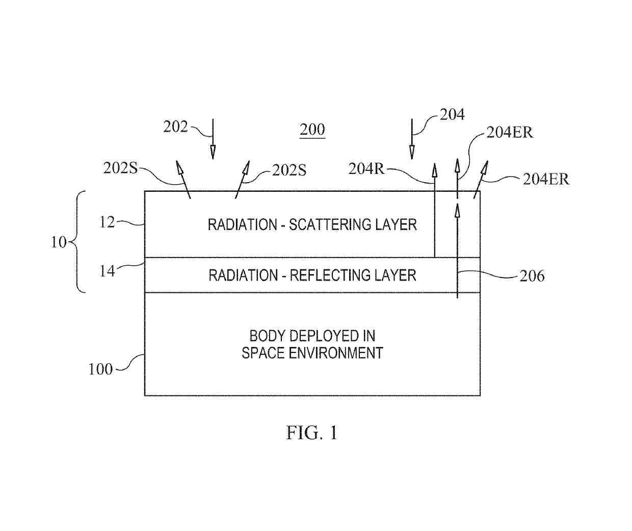
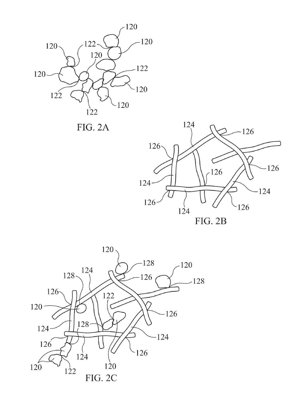
The present invention is about a covering for spacecraft structures that controls temperature. The covering is made up of two layers: a layer that lets light through and a layer that reflects and emits radiation. The first layer is made of small particles that scatter and reflect light. The second layer is made of a special material that reflects radiation at a specific wavelength. This covering system helps to keep the spacecraft cool during sunny conditions and warm during winter.

Problems solved by technology

There are many challenges involved in deep space exploration.
For example, current structure-coating technology used on space-based storage tanks, tank support struts, etc., limits the storage of liquid oxygen in deep space to days or weeks, i.e., not long enough to support a trip to Mars or operate a deep-space liquid oxygen storage depot.
Further, the operation of superconductors in space is limited as it is difficult to maintain superconductors at optimal low temperatures.

Method used


Image

  • Radiation reflector and emitter
  • Radiation reflector and emitter
  • Radiation reflector and emitter

Examples


Embodiment Construction

)

[0017]Referring now to the drawings and more particularly to FIG. 1, a multi-layer radiation reflector / emitter in accordance with an embodiment of the present invention is shown schematically and is referenced generally by numeral 10. As will be explained further herein, reflector / emitter 10 defines the framework for a novel composite structure that aids in controlling temperature of bodies that it covers or coats. In general, reflector / emitter 10 defines a novel composite structure for covering / coating spacecraft and spacecraft systems whose effective operation requires maintenance at very low temperatures, i.e., on the order of 75 K or less. Reflector / emitter 10 can be realized in a variety of ways depending on the type of “body” that is to be covered or coated. Accordingly, it is to be understood that the fabrication methods used to construct reflector / emitter 10 and / or apply / affix reflector / emitter 10 to a body are not limitations of the present invention.

[0018]In general, refl...


PUM


Abstract

A multi-layer radiation reflector / emitter includes first and second materials. The first material is transparent to radiation in a wavelength spectrum ranging from approximately 0.2 microns to at last 6 microns. The first material is a self-supporting arrangement of randomized particles having an average dimension in a range of approximately 0.2 microns to approximately 0.4 microns and defining a fill factor of approximately 0.1 to approximately 0.5. The second material reflects radiation having a wavelength greater than approximately 2 microns.

Description

CROSS-REFERENCE TO RELATED PATENT APPLICATION(S)[0001]This patent application claims the benefit of and priority to U.S. Provisional Patent Application Ser. No. 62 / 239,735, filed Oct. 9, 2015, the contents of which are hereby incorporated by reference in their entirety.ORIGIN OF THE INVENTION[0002]The invention described herein was made by employees of the United States Government and may be manufactured and used by or for the Government of the United States of America for governmental purposes without the payment of any royalties thereon or therefore.BACKGROUND OF THE INVENTION1. Field of the Invention[0003]This invention relates to the protection of structures from radiation heating. More specifically, the invention is a covering or coating that reflects and emits radiation over a broad wavelength spectrum.2. Description of the Related Art[0004]There are many challenges involved in deep space exploration. A number of these challenges can be advanced or even solved by the developme...

Claims


Application Information

Patent Timeline
IPC IPC(8): G02B5/08B64G1/58
CPCB64G1/58B64G1/226B64G1/503
Inventor YOUNGQUIST, ROBERT C.NURGE, MARK A.
Owner NASA
Learn More