Pipe fittings allowing non-destructive pressure testing of integrity of seals

a technology of integrity testing and pipe fittings, applied in the direction of pipe couplings, fluid tightness measurement, instruments, etc., can solve the problems of failure of welding joints of pe pipes, welding errors may occur, etc., and achieve the effect of improving flexibility in the use of fittings

Inactive Publication Date: 2019-04-30
PROPER PIPE EHF +1
View PDF17 Cites 0 Cited by
  • Summary
  • Abstract
  • Description
  • Claims
  • Application Information

AI Technical Summary

Benefits of technology

[0010]The fitting of the invention allows for rigorous testing of seal integrity, meaning that high pressure (e.g. 1-10 bar (0.1-1 MPa; 14-140 psi)) can be applied to the pressure test chambers adjacent to seals. The seals can conveniently be tested as a system is being put in place; after seals of a particular fitting have been welded to connecting tubes and allowed to cool, the can be tested, before or while the next connecting fitting is put in place. This means that each welding-cooling-testing cycle takes only about 12-15 minutes. A further advantage is that the seals can be tested at any time after completion of the system, such as many years later. By exposing the fitting the inlets to pressure chambers are again available for non-destructive testing, without the need to shut down the system or open the system itself.
[0011]Thus, the invention provides with the pressure testing chambers described herein rigorous active NDT; means to test repeatedly as often as desired, allowing for efficient monitoring and maintenance of a plumbing system.
[0024]As described in more detail herein below, the special configuration of the cold zones and sealing zones of the fittings of the present invention greatly improves flexibility in the use of the fittings. The fittings do not need clamps to maintain both pipe sections to be joined in a straight position, as the fittings can accommodate some bending / curvature, such as due to storage of pipe material in large coils.
[0025]A further very advantageous feature of the invention is the non-destructive nature of the testing of the integrity of the seals, through the arrangement of the pressure testing chambers of the fittings of the invention. The pressure testing chambers have inlets that are on the outside of the fitting and need no drilling or guiding of probes through the pipes. The inlets are in certain embodiments configured with valves, or valves can be part of external equipment used for pressure testing. The pressure testing chambers are formed in the sleeve portion of the fitting, the sleeve portion is dimensioned to allow for high pressure in the pressure chamber, allowing for testing with desired pressure. The sleeve portion typically has a wall thickness in the range of about 8-15 mm, such as preferably in the range 10-12 mm, such as about 10, 11 or 12 mm.DESCRIPTION OF THE INVENTION
[0028]An advantageous feature of the invention is the provision of multiple cold zones, these together with the multiple sealing zones provide for structural flexibility and thus can accommodate for some residual bending / curvature, which often is observed in pipes that have been stored coiled up. Accordingly, in an embodiment of the invention, there are provided in the fitting of the invention at least a first cold zone in between the first pair of sealing zones, a second cold zone in between the second pair of sealing zones (on the opposite end of the fitting) and at least one proximal cold zone in between said first and second cold zones. In another embodiment, there are two cold zones in between the first pair of sealing zones and two cold zones in between the second pair of sealing zones. In such embodiment, typically there is a cold zone between each sealing zone and the center of the region between the sealing zones There may further be provided two proximal cold zones in between the first and second pairs of sealing zones, such that e.g. one proximal cold zone is provided for between the fitting and each respective pipe end inserted into the fitting. In further preferred embodiments, the fitting extends beyond the distal (outer) sealing zones, to provide for further cold zones, on each end, distal to the respective pair of sealing zones. Thus, the fitting may in advantageous embodiments comprise from three and up to eight cold zones. Each cold zone preferably has a width in the range from 4 to 25 mm, more preferably a width in the range from 5 to 18 mm, or in the range from 6 to 15 mm or 5 to 15 mm, such as in the range from 8 to 12 mm, or in the range of 10-12 mm, such as e.g. 8 mm, 9 mm, 10 mm, 12 mm, 14 mm or 15 mm. The cold zones are preferably such that they fulfil the minimum parameters for cold zones designated by international standard EN 1555.

Problems solved by technology

Welded joints of PE pipes are however not always successful for reasons such as welding errors.
Welding errors may occur due to faults in cutting the pipes, lack of- or poor scraping, particles (debris) in the welding zone, positioner problems, humidity, incorrect welding parameters, etc.

Method used


Image

  • Pipe fittings allowing non-destructive pressure testing of integrity of seals
  • Pipe fittings allowing non-destructive pressure testing of integrity of seals
  • Pipe fittings allowing non-destructive pressure testing of integrity of seals

Examples


Embodiment Construction

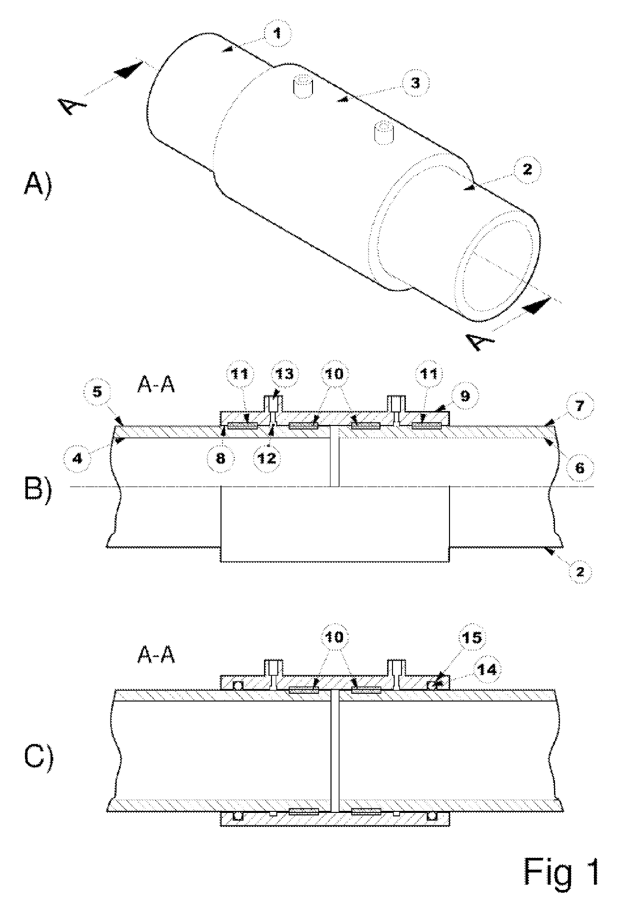
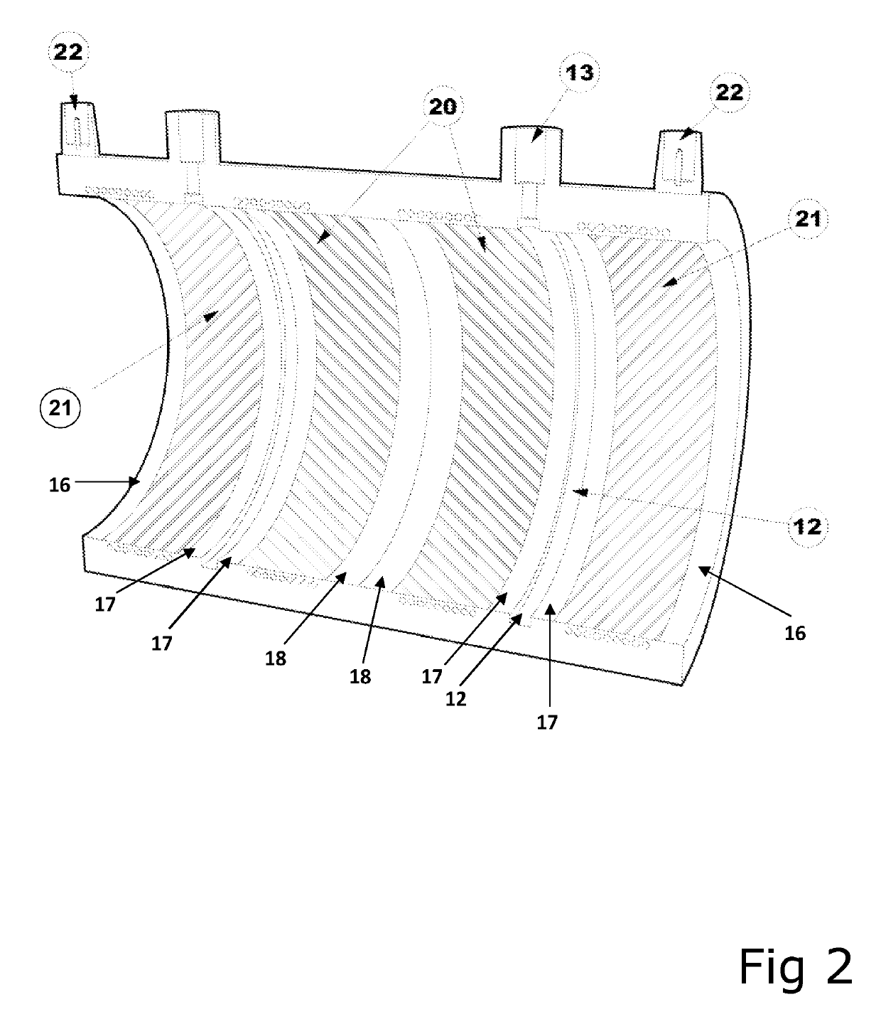
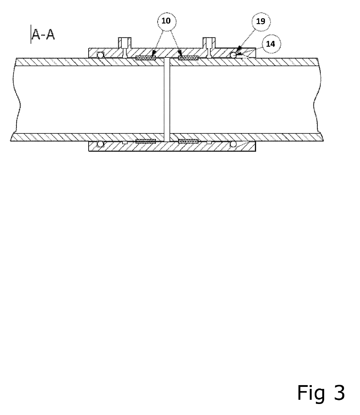
[0026]The following embodiments and definitions relate to the product and the test system of the present invention. Although most of the examples relate to electrofusion of PE pipes, other means of joining PE pipes or other pipes are anticipated by the invention, where a pressure chamber is created between two circular seals in the adjacent sealing zones and cold zones are used to enhance integrity.

[0027]In an embodiment of the present invention the first means for forming the first circular joint / seal between said inner surface of said sleeve and said outer surface of said first and / or second pipe section is means for forming a chemical fusion, friction welding, mirror welding or electrofusion.

[0028]An advantageous feature of the invention is the provision of multiple cold zones, these together with the multiple sealing zones provide for structural flexibility and thus can accommodate for some residual bending / curvature, which often is observed in pipes that have been stored coiled...


PUM

PropertyMeasurementUnit
widthaaaaaaaaaa
widthaaaaaaaaaa
thicknessaaaaaaaaaa

Abstract

Fittings to join and tightly seal tubes such as plastic tubes used in but not limited to various plumbing applications. The fittings allow for rigorous and non-destructive tests of the integrity of seals, where the integrity of seals can be readily and quickly tested one by one, as a pipe system is being built. The seals can also be tested again, after installation and completion of the plumbing arrangement. The fitting comprises two pairs of sealing zones, each pair having in between sealing zones a pressure testing chamber with an inlet, which allows for pressurizing the chamber and testing the integrity of the adjacent seals. The fittings have a series of cold zones that enhance flexibility and integrity of the fittings.

Description

FIELD OF THE INVENTION[0001]The present invention relates to pipe fittings and a testing device and system for testing the quality and integrity of the fusion seals made by electrofusion or other sealing methods between two pipes in a non-destructive manner.BACKGROUND OF THE INVENTION[0002]Polyethylene (PE) is commonly used in manufacturing plastic pipes for gas and water supply, where high density polyethylene (HDPE) is the most common ingredient. When laying PE pipes or fixing ruptured or broken pipes, the PE pipes are typically joined using fusion welding such as butt fusion, electrofusion or hot iron fusion.[0003]In general an electrofusion fitting comprises tubular openings adapted to receive a pipe to be connected to the fitting. An electrofusion element is arranged in the tubular opening at the inner surface to be adjacent to the outer surface of the pipe which is inserted into the fitting. A common electrofusion element consists of an electrical heating coil of resistance wi...

Claims


Application Information

Patent Timeline
Patent Type & Authority Patents(United States)
IPC IPC(8): F16L47/03G01M3/28B29C65/00B29C65/34F16L55/00F16L47/30B29C65/82B29C65/06B29C65/20
CPCF16L55/00B29C65/342G01M3/2853F16L47/30F16L47/03B29C66/52296B29C66/52241B29C66/52231B29C65/3432B29C65/8246B29C66/112B29C66/114B29C66/1122B29C66/131B29C66/232B29C66/5221B29C66/5224B29C66/5229B29C66/71B29C65/3476B29C65/3468B29C65/20B29C65/06B29K2023/06B29K2023/065B29K2055/02B29K2023/12B29K2027/16B29K2027/06F16L47/32F16L2201/30
Inventor MENCOS, RUBEN
Owner PROPER PIPE EHF
Why Eureka
Try Eureka