Scalar atomic magnetometer with heading error suppression

Active Publication Date: 2019-04-30
AOSENSE
View PDF9 Cites 16 Cited by
  • Summary
  • Abstract
  • Description
  • Claims
  • Application Information

AI Technical Summary

Problems solved by technology

This problem is known as heading error, wherein the magnetometer is sensitive to its orientation relative to the direction of the magnetic field.
Other e

Method used


Image

  • Scalar atomic magnetometer with heading error suppression
  • Scalar atomic magnetometer with heading error suppression
  • Scalar atomic magnetometer with heading error suppression

Examples


Embodiment Construction

[0020]The invention can be implemented in numerous ways, including as a process; an apparatus; a system; a composition of matter; a computer program product embodied on a computer readable storage medium; and / or a processor, such as a processor configured to execute instructions stored on and / or provided by a memory coupled to the processor. In this specification, these implementations, or any other form that the invention may take, may be referred to as techniques. In general, the order of the steps of disclosed processes may be altered within the scope of the invention. Unless stated otherwise, a component such as a processor or a memory described as being configured to perform a task may be implemented as a general component that is temporarily configured to perform the task at a given time or a specific component that is manufactured to perform the task. As used herein, the term ‘processor’ refers to one or more devices, circuits, and / or processing cores configured to process da...


PUM


Abstract

An atomic magnetometer includes a vapor cell, one or more pumping lasers, a probe laser, and a sensor. The one or more pumping lasers are disposed to direct one or more laser beams though the vapor cell to interact with atoms of an atomic vapor in the vapor cell. The atomic vapor periodically absorbs light of alternating circular polarization from the one or more laser beams. The probe laser is disposed to direct polarized light to pass through the vapor cell. The sensor is disposed to intersect the polarized light from the probe laser after passing through the vapor cell.

Description

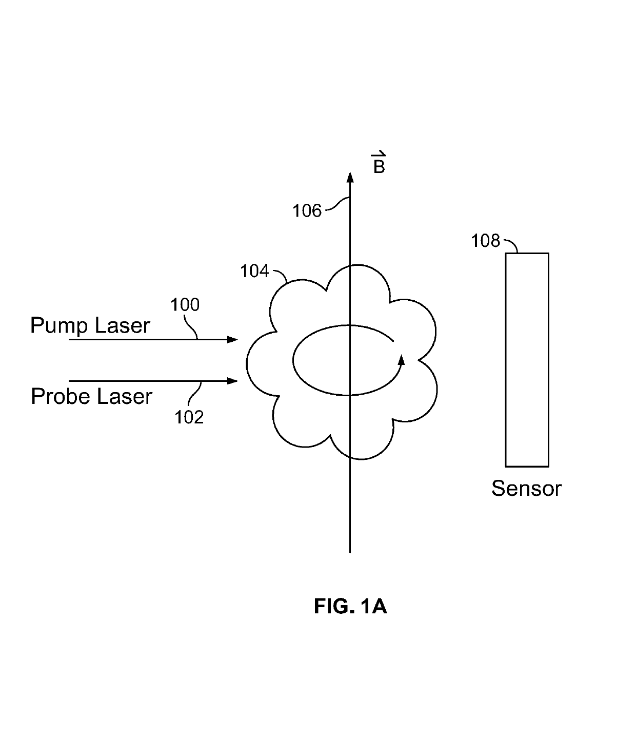
[0001]This invention was made with Government support under contract #N68335-14-C-0201 awarded by the US Navy. The Government has certain rights in the invention.BACKGROUND OF THE INVENTION[0002]Scalar atomic magnetometers are capable of very precisely measuring a magnetic field strength by optically pumping an atomic vapor and measuring the Larmor precession frequency of the atomic spins within the vapor using a probe laser. An ideal scalar atomic magnetometer measures the magnitude of the magnetic field strength without regard to its direction. However, when the pump laser is circularly polarized and not perpendicular to the magnetic field, nonlinear Zeeman shifts cause the atomic vapor resonance to asymmetrically shift, registering as a small shift in the measured magnetic field. This problem is known as heading error, wherein the magnetometer is sensitive to its orientation relative to the direction of the magnetic field. Other effects such as light shifts or phase shifts associ...

Claims


Application Information

Patent Timeline
IPC IPC(8): G01R33/26G01N24/00
CPCG01R33/26G01N24/006
Inventor LEDBETTER, MICAHPATTON, BRIAN
Owner AOSENSE
Why Eureka
Try Eureka