Excited state atomic line filters

Inactive Publication Date: 2006-06-06
TREX ENTERPRISES CORP
View PDF2 Cites 9 Cited by
  • Summary
  • Abstract
  • Description
  • Claims
  • Application Information

AI Technical Summary

Problems solved by technology

One problem with atomic line filters such as those referred to above is that their operation depends on the existence of a good sharp resonant absorption line near the spectral range to be filtered.

Method used


Image

  • Excited state atomic line filters
  • Excited state atomic line filters
  • Excited state atomic line filters

Examples


embodiment

PREFERRED EMBODIMENT

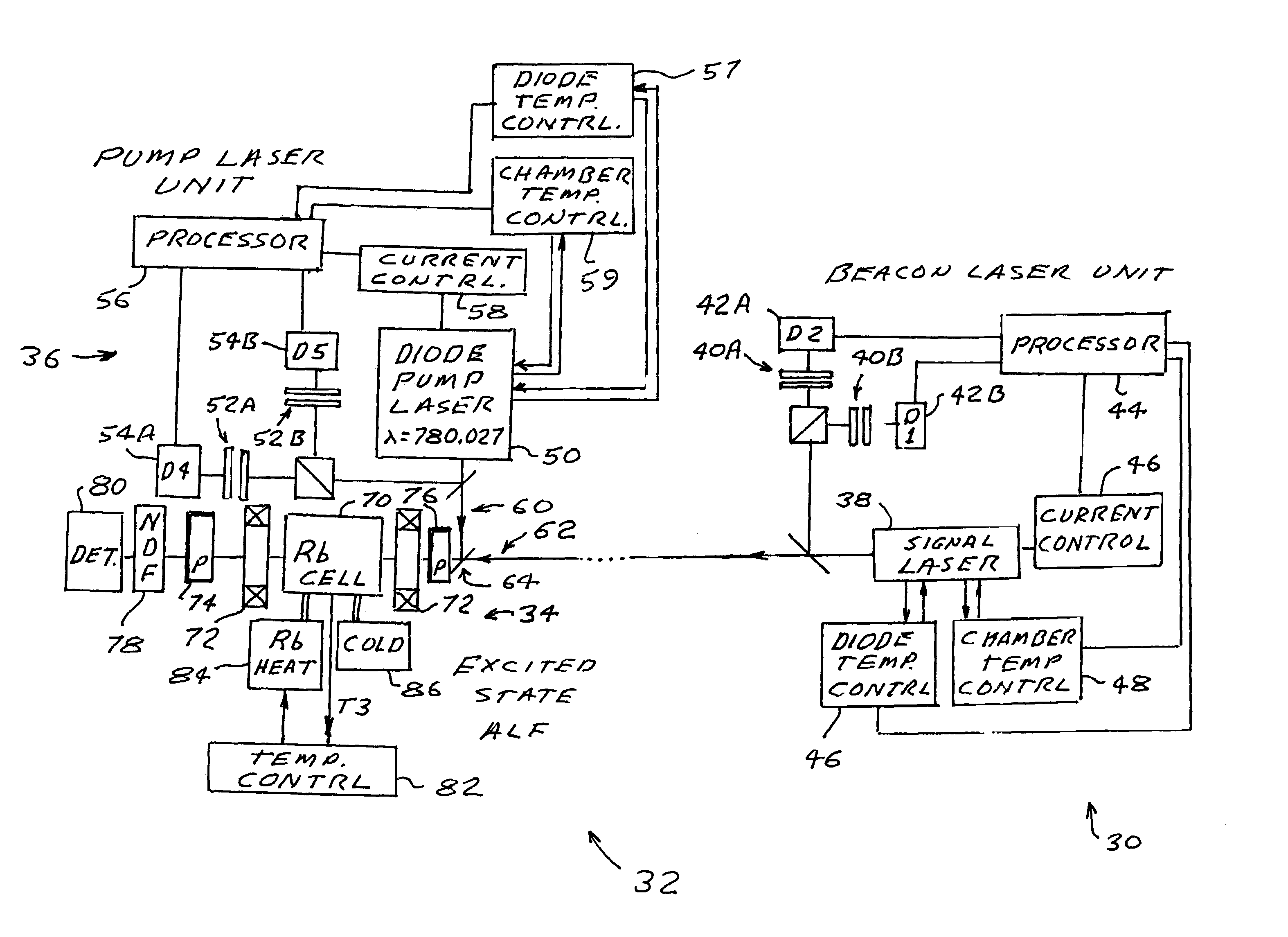
[0059]Details of the principal components and features of a preferred embodiment of the present invention are shown in FIGS. 3, 3A, 3B, and 3C. This embodiment includes a beacon laser unit 30 that might be located on a moving platform such as an unmanned aerial vehicle such as those shown in FIG. 9. It also includes excited state atomic line filter unit 32 comprising rubidium ALF 34 and pump laser unit 36.

[0060]The beacon laser unit comprises diode signal laser 38, frequency locking etalons 40A and 40B, and detectors 42A and 42B providing frequency locking signals to processor 44 which utilizes those signals to control the current to signal laser 38 through current control 46. Processor 44 also maintains control of the diode temperature and the chamber temperature through thermoelectric coolers (not shown) and diode temperature control unit 46 and chamber temperature control unit 48.

[0061]Pump laser unit 36 provides a laser beam locked precisely to a wavelength λ...


PUM


Abstract

An excited state atomic line filter. The present invention solves the problem of lack of ground state resonant lines in at wavelengths substantially longer than those of visible light. Atomic line filters of the Faraday or Voigt crossed polarizer type are provided in which alkali metal atomic vapor in a vapor cell is excited with a pump beam to an intermediate excited state where a resonant absorption line, at a desired wavelength, is available. A magnetic field is applied to the cell producing a polarization rotation for polarized light at wavelengths near the resonant absorption lines. Thus all light is blocked by the cross polarizers except light near one of the spaced apart resonant lines. However, the polarization of light at certain wavelengths near the resonant is rotated in the cell and therefore passes through the output polarizer.

Description

[0001]The present invention related to optical filters and especially to atomic line filters (ALF).BACKGROUND OF THE INVENTION[0002]Atomic line filters are a class of optical filters which have acceptance bandwidths on the order of 0.001 nm. In one prior art type of ALF, broadband light containing narrowband signal light is passed through a first color glass filter which cuts off light at wavelengths below a threshold value. The signal and remaining noise light enter an atomic vapor that only absorbs the signal light within the atom's 0.001 nm acceptance bandwidth thereby exciting those absorbing atoms to an intermediate energy level. A pump beam further excites those atoms to a second, higher energy level that then decays through various processes including fluorescence, to the ground state of the atom. The emitted fluorescence occurs at wavelengths below the threshold value of the first color glass filter. A second color glass filter then cuts off any wavelengths above the thresho...

Claims


Application Information

Patent Timeline
Patent Type & Authority Patents(United States)
IPC IPC(8): H01S3/22H01S3/10H01S3/13
CPCH01S3/1303H01S3/10
Inventor ZHAO, ZHONG-QUANLEFEBVRE, MICHAEL JOSEPHLESLIE, DANIEL H.
Owner TREX ENTERPRISES CORP
Why Eureka
Try Eureka