Eureka AIR delivers breakthrough ideas for toughest innovation challenges, trusted by R&D personnel around the world.

Method for fabricating an electromagnetic induction digitizer antenna board

a technology of electromagnetic induction and antenna boards, applied in the field of antenna boards, can solve the problems of difficult realization, low yield rate, and difficult maintenance, and achieve the effects of low yield rate, thin electronic structure, and high production cos

Active Publication Date: 2019-04-30
WU YINGCHAO +2
View PDF9 Cites 0 Cited by
  • Summary
  • Abstract
  • Description
  • Claims
  • Application Information

AI Technical Summary

Benefits of technology

[0003]The present invention provides a solution to the technical difficulty of the coiling and positioning of the conductive wires when fabricating the electromagnetic induction digitizer antenna board. The present invention further provides a solution to another technical difficulty that the electromagnetic induction digitizer antenna board includes many bridging connections, to which the solutions given by the conventional technologies are very complex. An objective of the present invention is to solve the following technical difficulties of the conventional technologies: during the fabrication of the electromagnetic induction digitizers, the conductive wire coiling or printing is often featured with a low yield rate and high production cost, expansive equipment and thick antenna boards, which cannot satisfy the desire for thinner electronic devices. The present invention also provides a solution to the technical difficulty of conductive wires which are often curve due to the pulling when binding the conductive wires. The present invention is featured with a lower production cost, a better quality consistence, a higher yield rate, and the production equipment is less complex with a relatively well-developed fabrication technology of electromagnetic induction digitizer antenna board.
[0026]According to the present invention, the substrate can be adaptively selected from papery, leathery or fabric materials, preferably having a mesh structure. Such materials are more convenient for being holed for fixing or binding the wires. The computer-aided embroidery machine, the quilt sewing machine, or the single-needle single-thread chain-stitch sewing machine are well developed, and the present invention employs such machines for binding the conductive wires, so that it is convenient to use the computer-aided embroidery design software to design the layout of the electromagnetic induction coils and bind them with binding threads.
[0027]The present invention has the following advantages: the present invention employs well developed computer-aided embroidery machine for binding the conductive wires, thus drastically saving fabrication and design cost; cheap threads can be used as serving as the binding threads, and low-cost substrate can be used and therefore the total cost could be very low; only one fabrication procedure, i.e., embroidery procedure, is needed for all the fabrication process, and therefore the working procedure is much simplified; there is no pollutes produced during the fabrication process, and therefore comparing the conventional technologies, the present invention is more environment friendly; the needle head of the computer-aided embroidery machine can be selected very sharp, even smaller than 0.1 mm, and thus capable of making very dense needle stitches, and in this manner, during the layout design, very small line distance is practical and realizable, so that the present invention is capable of realize the production of small size and super large antenna boards, which is even impossible for conventional technologies. The stitching process realizes the binding of the conductive wires, and has no adverse effect to intersections of the conductive wires, thus providing a perfect solution to the bridging connections. According to the present invention, an antenna board including an X-axle antenna and a Y-axle antenna which are overlapped each other can be configured on a single substrate. Such an antenna board is much thinner than that of the conventional layer by layer fabrication technology. Using elastic threads as the binding threads prevents the technical problem of conductive wires are often curve due to the pulling when binding the conductive wires, thus saving the binding threads and improving the positioning accuracy. Conventional technologies often adopt multi-layer bridging connections for antenna boards having overlapped multi-layer electromagnetic induction coils. In comparison, the present invention is adapted for realize sophisticated bridging connection among electromagnetic induction coils on the same layer of substrate. As such, the present invention greatly decreases the thickness of the electromagnetic digitizer control board, and is more desirable for the thinner electronic appliances. An additional procedure of rolling pressing the electromagnetic induction coils and the substrate may advantageously position all the electromagnetic induction coils at the same level.

Problems solved by technology

However, doing this requires large investment in equipment development, and particularly it is very difficult to realize, and the equipment are often complicate for operation, not reliable, and hard for maintenance.
Therefore, this approach may hardly save cost, and so far the technology is far from workable.
However, one of the biggest difficulties of such technology is that there are too many intersection points between coils.
As such, when there are many intersection points, the process will be very slow, and the working efficiency will also be low.
In addition, it also leads to additional machine depreciation, as well as other problems such as wire breaking.
Unfortunately, such an approach makes the antenna board much thicker, and also introduces additional difficulty to the fabrication.
In summary, the conventional technologies for fabricating antenna boards of electromagnetic induction digitizers mainly have the following defects: regarding the conventional thin film type and printing circuit board type antennas, the cost is very high and it's very difficult to fabricate large-size antennas; regarding the manual coiling method, the working efficiency is low, and it requires a lots of manpower, and further the product quality is often inconsistent, thus the production yield will be low; regarding the complex automatic coiling machine, the equipment is usually very expensive, and complicate to maintain, while the technology is still under-development, and thus difficult to extensively use; as to the ultrasonic embedding equipment which is relatively well used, the technology is still too complicate, the working efficiency is still low, and the antenna board is thick.

Method used


Image

  • Method for fabricating an electromagnetic induction digitizer antenna board
  • Method for fabricating an electromagnetic induction digitizer antenna board
  • Method for fabricating an electromagnetic induction digitizer antenna board

Examples


first embodiment

[0049

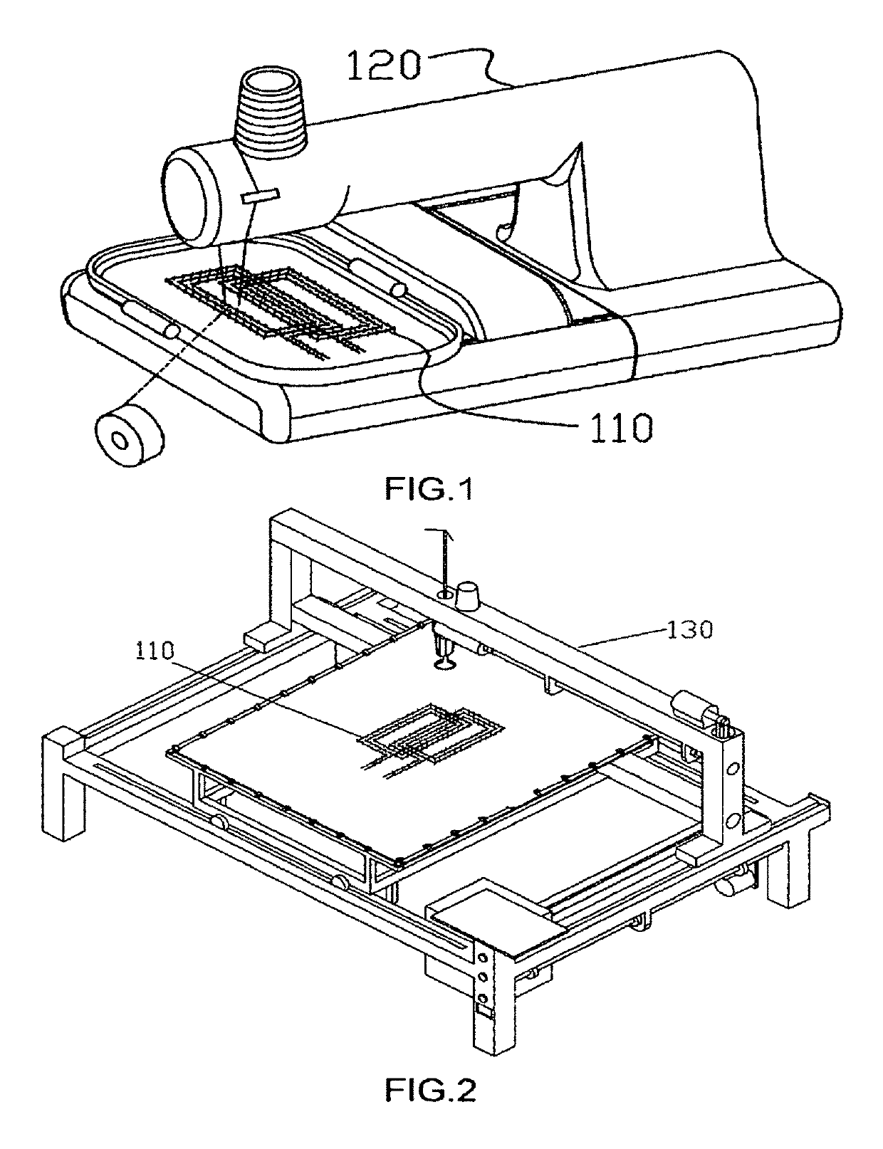
[0050]FIG. 1 is a schematic diagram illustrating a computer-aided embroidery machine outputting a conductive wire and a binding thread. Referring to FIG. 1, according to an embodiment of the present invention, a method for fabricating an electromagnetic induction digitizer antenna board. The method includes the following steps. At first, a flat substrate for attaching with an electromagnetic induction coil is prepared, wherein the substrate is adapted for being holed with through holes. The substrate can be adaptively selected from papery material, leathery material, fabric material, weaving textile material, artificial leathery material, and plastic material. Then, a consecutive wire leading-out terminal is provided at one side of the substrate for configuring an electromagnetic induction coil. The consecutive wire leading-out terminal is adapted for outputting a conductive wire therefrom. The consecutive wire leading-out terminal outputs and coils to configure the electromagn...

second embodiment

[0051

[0052]FIG. 2 is a schematic diagram illustrating a quilt sewing machine 130 outputting a conductive wire and a binding thread. Referring to FIG. 2, similar to the first embodiment, the quilt sewing machine has a surface thread output terminal or a bottom thread output terminal. According to one aspect of the embodiment, the surface thread output terminal serves as the consecutive wire leading-out terminal to output and coil the electromagnetic induction coil, and correspondingly the bottom thread output terminal serves as the binding thread output terminal to output the binding thread for binding and fixing the conductive wires. According to another aspect of the embodiment, the bottom thread output terminal serves as the consecutive wire leading-out terminal to output and coil the electromagnetic induction coil, and correspondingly the surface thread output terminal serves as the binding thread output terminal to output the binding thread for binding and fixing the conductive ...

third embodiment

[0053

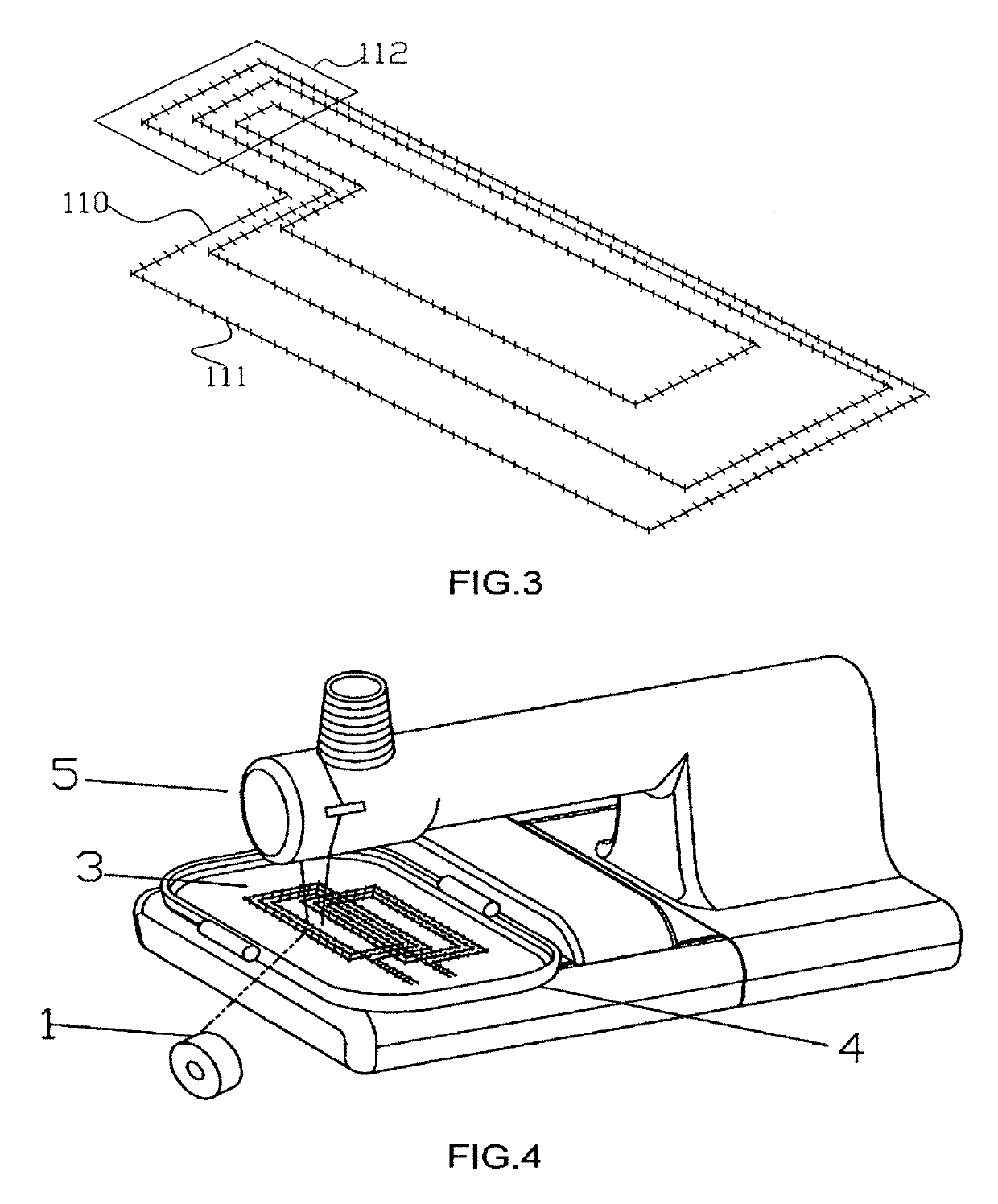
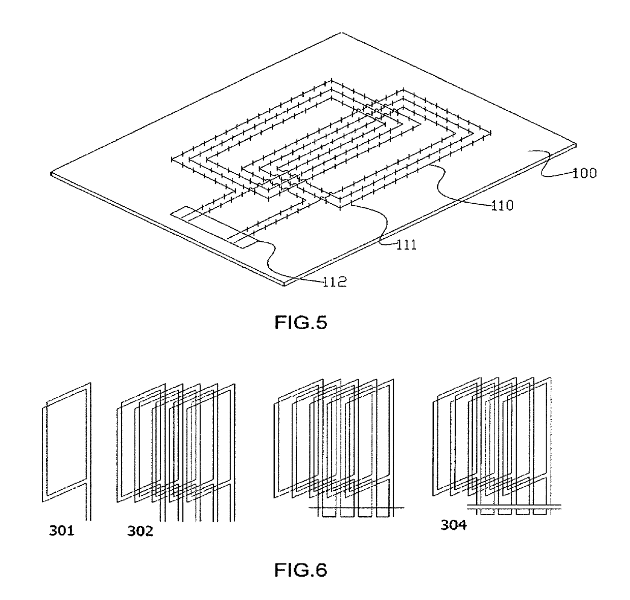
[0054]FIG. 3 is a schematic diagram illustrating a single-needle single-thread chain-stitch sewing machine outputting a binding thread. Referring to FIG. 3, the single-needle single-thread chain-stitch sewing machine has a surface thread output terminal but does not need bottom threads. A mechanical arm having a wire output opening is provided serving as the conductive wire leading-out terminal, and the surface thread output terminal of the single-needle single-thread chain-stitch sewing machine serves as the automatic conductive wire binding mechanism. The wire output opening outputs the conductive wires and configures the electromagnetic induction coils 110, and the surface thread output terminal of the single-needle single-thread chain-stitch sewing machine outputs the binding threads 111 to bind and fix the electromagnetic induction coils 110. The wire output opening moves together with the machine head of the single-needle single-thread chain-stitch sewing machine along wi...


PUM


Abstract

A method for fabricating an electromagnetic induction digitizer antenna board that includes the steps of: a. preparing a substrate that is convenient for being holed; b. providing a consecutive wire leading-out terminal at one side of the substrate; c. moving the substrate relative to the consecutive wire leading-out terminal along with a predetermined track of the electromagnetic induction coil of the induction digitizer antenna board, so that the consecutive wire leading-out terminal gets in surface-contact with the substrate, and configures the electromagnetic induction coil on the substrate; d. binding the conductive wire of the electromagnetic induction coil with the substrate at every predetermined interval.

Description

BACKGROUND OF THE INVENTION[0001]The present invention relates to an antenna board, and particularly to a method for fabricating an electromagnetic induction digitizer antenna board adapted for handwriting input.[0002]Currently, electromagnetic induction antennas for handwriting input are usually fabricated by the printing technology, in which multiple layers of printed circuits are stacked one on another to achieve induction positioning of a plurality of electromagnetic induction coils. Regarding the antenna fabricating technology for large-size electromagnetic induction digitizer, people skilled in the art tried to realize the automatic coiling of metal wires by simulating the manual coiling method. However, doing this requires large investment in equipment development, and particularly it is very difficult to realize, and the equipment are often complicate for operation, not reliable, and hard for maintenance. Therefore, this approach may hardly save cost, and so far the technolo...

Claims


Application Information

Patent Timeline
Patent Type & Authority Patents(United States)
IPC IPC(8): H01P11/00H01Q13/00H01Q7/00H04B5/00
CPCH04B5/0081H01Q7/00
Inventor WU, YINGCHAOCHEN, SONGLUO, HANG
Owner WU YINGCHAO
Why Eureka
Eureka Blog
Learn More