Tire arrangement implement and tire arrangement method

a technology of tire arrangement and implement, which is applied in the direction of wheel mounting apparatus, instruments, and static/dynamic balance measurement, can solve the problems of achieve the effect of reducing or preventing rubbing and deformation of decorative portions 18 and preventing deformation and deformation of decorative portions 10

Active Publication Date: 2019-05-07
THE YOKOHAMA RUBBER CO LTD
View PDF24 Cites 0 Cited by
  • Summary
  • Abstract
  • Description
  • Claims
  • Application Information

AI Technical Summary

Benefits of technology

[0005]The present technology provides a tire arrangement implement and a tire arrangement method capable of preventing blemishes that detract from the appearance of the tire.
[0009]With the tire arrangement implement and the tire arrangement method of the present technology, the spacer separates the decorative portion of one tire from another tire or the peripherally located member when a plurality of tires are arranged in a row. Accordingly, rubbing and deformation of the decorative portion is reduced or prevented, and blemishes that detract from the appearance of the tire are prevented, which is advantageous.

Problems solved by technology

When this happens, the decorative portions located on the sidewall portions experience rubbing or deformation and blemishes that detract from the appearance of the decorative portions are formed.

Method used


Image

  • Tire arrangement implement and tire arrangement method
  • Tire arrangement implement and tire arrangement method
  • Tire arrangement implement and tire arrangement method

Examples


modified examples

[0081]FIGS. 6 to 9 are explanatory views of modified examples of the tire arrangement implement illustrated in FIG. 4. FIG. 6 is a plan view of the first modified example of the tire arrangement implement 1. FIG. 7 is a cross-sectional view of the tire arrangement implement 1 of FIG. 6 taken along B-B. FIG. 8 is a plan view of the second modified example of the tire arrangement implement 1. FIG. 9 is a cross-sectional view of the tire arrangement implement 1 of FIG. 8 taken along C-C. Note that the dashed lines in FIGS. 6 and 8 represent an imaginary circles formed by connecting the inner circumferential surface and outer peripheral surface of the spacers 2.

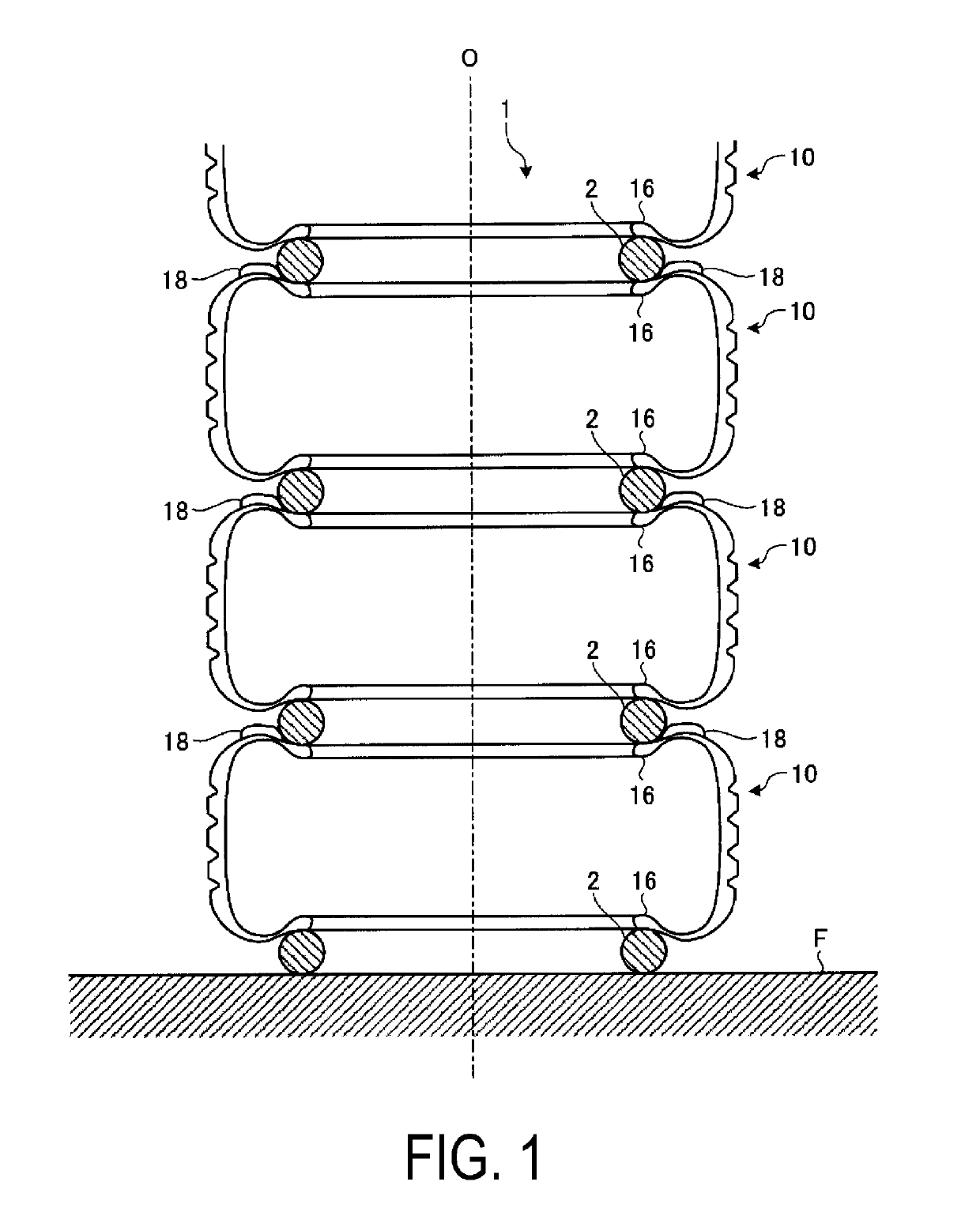
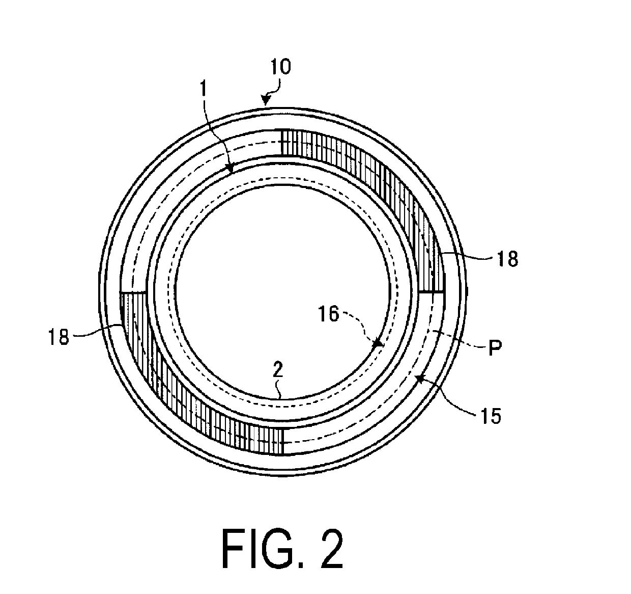
[0082]In the configuration illustrated in FIG. 4, as described above, the spacer 2 has an annular structure continuous in the circumferential direction. With such a configuration, contact surface of the spacer 2 and the tire 10 is ensured to a considerable degree. Thus, the spacer 2 and the tire 10 (the bead portion 16 in FIG. 1)...

examples

[0166]FIG. 36 is a table showing results of performance testing of pneumatic tires according to the embodiment of the present technology. FIG. 37 is an explanatory view illustrating a tire arrangement method of a conventional example.

[0167]In the performance testing, various tires provided with a decorative portion (colored portion or fin) located in a prescribed region on the sidewall portion were observed for blemishes that detract from the appearance of the decorative portion when four individual tires were arranged stacked with the tire rotational axes thereof aligned. Then, the number of locations where blemishes formed on the four tires was totaled and evaluated. In this evaluation, a smaller value is preferable. Note that the tire size of each tire was 195 / 65R15 91H.

[0168](1) The performance testing of tires with a colored portion as the decorative portion was carried out as follows. First, four individual tires were arranged stacked vertically on a tire cart with the tire ro...


PUM


Abstract

The tire arrangement implement is employed to arrange a plurality of tires, each provided with a decorative portion located on a sidewall portion, in a row in the tire rotational axis direction. The tire arrangement implement comprises a spacer. The spacer is disposed between adjacent tires or between the tire and the floor, not in contact with the decorative portion, and separates the decorative portion of one tire from another tire or the peripherally located member.

Description

TECHNICAL FIELD[0001]The present technology relates to a tire arrangement implement and a tire arrangement method, and particularly relates to a tire arrangement implement and a tire arrangement method capable of preventing blemishes that detract from the appearance of a tire.BACKGROUND ART[0002]Conventionally, upon storage, transport, or display of tires, a method of arranging a plurality of tires or a plurality of tire-wheel assemblies in a row in the tire rotational axis direction has been widely employed. Examples of methods that have been employed include a method of arranging a plurality of tires on the floor stacked in a row with the tire rotational axes thereof vertically facing.[0003]The technologies described in Japanese Unexamined Patent Application Publication No. 2004-268665A and Japanese Patent No. 4899995B are such known conventional tire arrangement methods.[0004]However, upon storage, transport, or display of tires, the side surfaces of adjacent tires come into cont...

Claims


Application Information

Patent Timeline
Patent Type & Authority Patents(United States)
IPC IPC(8): B65D85/02B65D57/00B65D85/06B60B30/08A47F7/04B60C19/00
CPCA47F7/04B60B30/08B65D85/06B65D57/00B60C19/00B65D57/003
Inventor MINAMI, YUJIKUWAJIMA, MASATOSHI
Owner THE YOKOHAMA RUBBER CO LTD
Why Eureka
Try Eureka