Deployable structure for use in establishing a reflectarray antenna

a technology of deployable structure and reflector, which is applied in the field of deployable structure, can solve the problems of difficult to understand the deployment kinematics and reliability challenges, and the phased-array antenna typically requires a complicated and/or expensive feed network and amplifier structure, and achieves the effect of convenient tape deployment and convenient positioning of the deployed reflector

Active Publication Date: 2019-05-07
M M A DESIGN
View PDF22 Cites 6 Cited by
  • Summary
  • Abstract
  • Description
  • Claims
  • Application Information

AI Technical Summary

Benefits of technology

[0011]In yet another embodiment of the deployable structure, the endless pantograph comprises at least three composite linear sub-pantographs with each of the at least three composite linear sub-pantographs having a first linear pantograph that is interlaced with, pivotally connected to, and offset relative to a second linear pantograph (i.e., an interlaced linear pantograph in which the two pantographs lie in the same plane). An offset of 180° provides the greatest increase in stiffness relative to endless pantograph with sides formed by a single set of linear sub-pantographs. However, other offsets are feasible. A vertex structure extends between each end of a composite linear sub-pantograph and the end of an adjacent composite linear sub-pantograph. In this embodiment, the composite linear sub-pantographs that form each side of the endless pantograph can be characterized as composite interlaced linear sub-pantographs. The endless pantograph structure with composite linear sub-pantographs that each employ two interlaced linear sub-pantographs has an undeployed perimeter length that is greater than the perimeter length of a comparable endless pantograph with composite linear sub-pantographs that each employ stacked sub-pantographs (i.e., an endless pantograph with stacked linear sub-pantographs that substantially has the same perimeter length as the endless pantograph with interlaced linear sub-pantographs when fully deployed).
[0013]Yet another embodiment of the deployable structure employs a limiter to limit the extent to which the endless pantograph is deployed. In one embodiment, the limiter includes a plurality of pins with each pin associated with a first leg of the endless pantograph and adapted to engage a second leg of the endless pantograph to which the first leg is pivotally attached in a manner that prevents relative rotation between the first and second legs once a desired angle between the first and second legs is reached during deployment. In a particular embodiment, a pin is associated with the two pivot joints located at the ends of each leg comprising the endless pantograph. The use of these pins, at least in endless pantographs with polygonal shapes, serves to limit the deployment of the endless pantograph, distribute the load, and reduce bowing in the deployed linear sub-pantographs (particularly when relatively long sub-pantographs are employed).
[0014]In a particular embodiment of the deployable structure, the energy providing device includes one or more springs that provide the energy for transitioning the endless pantograph and the flexible reflectarray from the undeployed state towards the deployed state. In a particular embodiment, the energy providing device comprises a spring associated with each pivot connection between the legs that form the endless pantograph. When the endless pantograph is in the undeployed state, the springs cumulatively store sufficient potential energy to transition the endless pantograph from the undeployed state to the deployed state. In the regard, when the restraint on the endless pantograph that maintains the endless pantograph in the deployed state is removed or reduced, the springs cause the legs that comprise the endless pantograph to rotate relative to one another and thereby transition the pantograph from the undeployed state towards the deployed state. Once the endless pantograph is in the deployed state, the springs store less potential energy than in the undeployed state but sufficient potential energy to maintain the endless pantograph in the deployed state based on the forces the deployed pantograph and reflectarray are reasonably expected to encounter in the relevant application. It should also be appreciated that by the use of multiple springs and the use of the multiple springs to store more potential energy than is needed to deploy and maintain the deployment of the endless pantograph and flexible reflectarray the failure of one or more springs can be accommodated.
[0015]In another embodiment of the deployable structure, the deployment mechanism includes a deployable tape structure for establishing a spatial relationship between the flexible reflectarray and another component of a reflectarray antenna. For instance, the deployable tape structure can be used in establishing the position of a feed antenna, subreflector, or reflectarray subreflector relative to the flexible reflectarray. In a particular embodiment, the deployment structure includes at least three deployable tapes, each tape extending from a first end that is operatively engaged to the endless pantograph to a second end that is operatively connected to an element that facilitates the positioning of the deployed reflectarray (supported by deployed endless pantograph) relative to another component of a reflectarray antenna. In a particular embodiment, the second end of each of the tapes is operatively connected to or adjacent to a feed antenna of the reflectarray antenna. In the deployed state, the three tapes contribute to the positioning of the deployed endless pantograph and the deployed reflectarray relative to the feed antenna in a reflectarray antenna. More specifically, the deployed tapes and the deployed endless pantograph substantially define a pyramidic or conic structure. In a particular embodiment, at least two of the tapes are of different lengths. As such, the deployable structure, when fully deployed, establishes the reflectarray and the feed antenna in a configuration known as a reflectarray antenna with an offset feed, i.e., the boresight of the feed antenna is not parallel to a line perpendicular to the deployed reflectarray. Further, the deployed reflectarray, the endless pantograph, and the deployed tapes substantially define an oblique pyramid or oblique cone. In a specific embodiment, each of the tapes transitions between an undeployed state characterized by a substantially portion of the tape being in a roll and a small portion of the tape extending linearly and a deployed state characterized by a substantial portion of the tape extending linearly. Further, each of the tapes is preferably a quasi-dual stable tape that exhibits: (a) a first stable state when the entire tape is wound or rolled, (b) a second stable state when the entire tape is straight, and (c) a propensity to transition towards the second stable state when a portion of the tape is in the first state and another portion of the tape is in the second state. As such, when a significant portion of the tape is rolled but a portion of the tape is straight or extends linearly, the tape is storing energy that can subsequently be used to transition the tape towards the second stable state. The use of such tapes facilitates the deployment of the tapes between the undeployed and deployed states.

Problems solved by technology

However, the phased-array antenna typically requires a complicated and / or expensive feed network and amplifier structures.
Characteristic of such a deployable reflectarray are difficulties in understanding the deployment kinematics and reliability challenges, particularly in space-based applications.

Method used


Image

  • Deployable structure for use in establishing a reflectarray antenna
  • Deployable structure for use in establishing a reflectarray antenna
  • Deployable structure for use in establishing a reflectarray antenna

Examples


Embodiment Construction

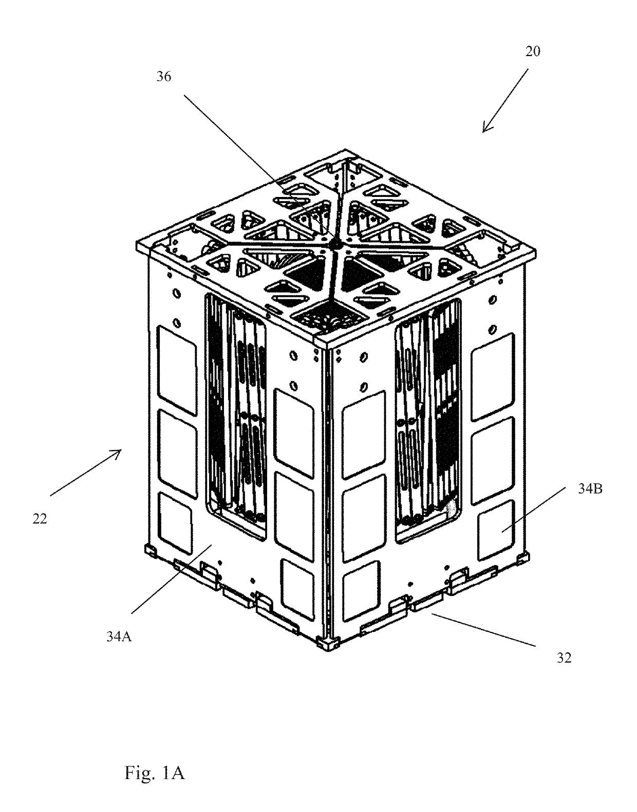
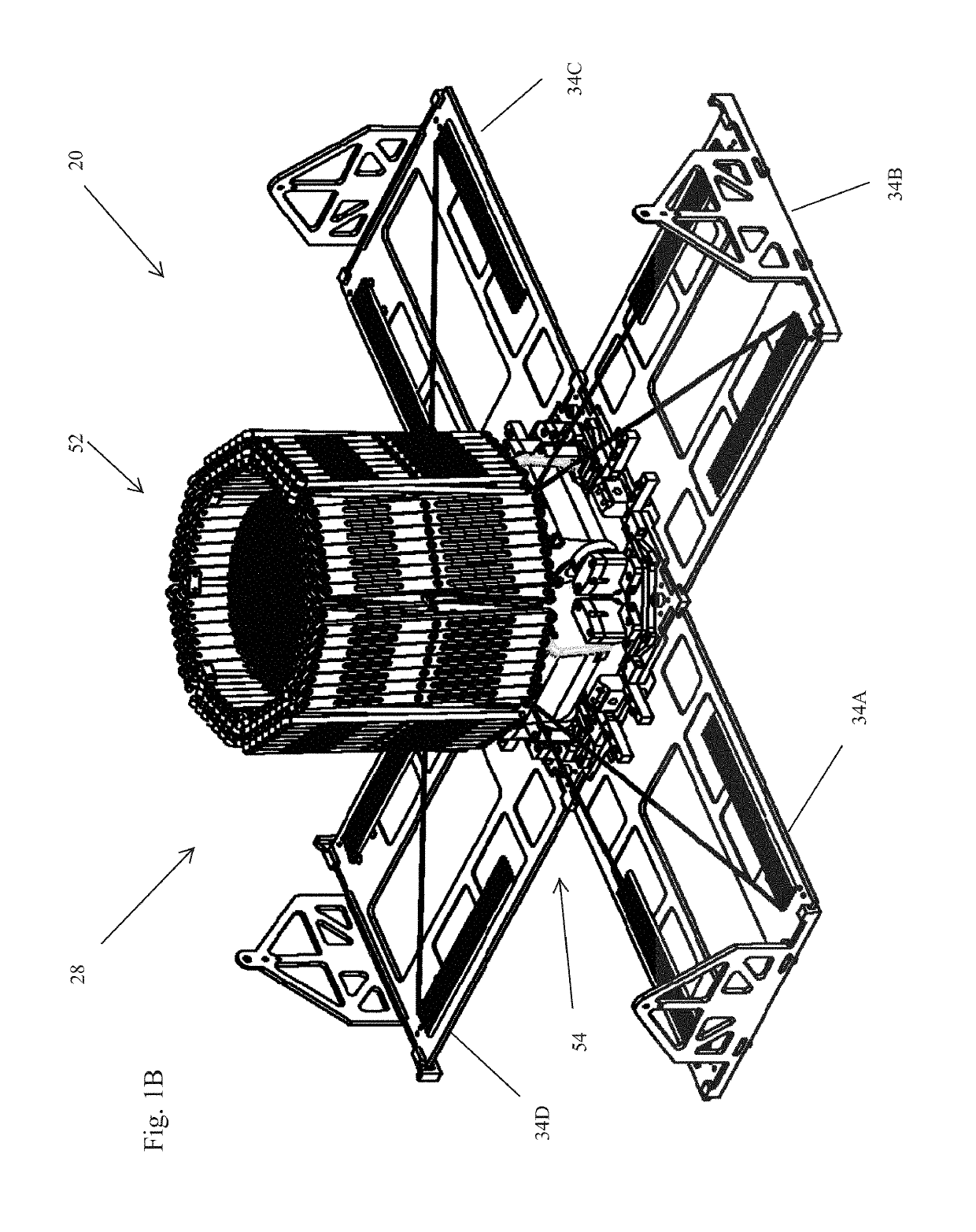
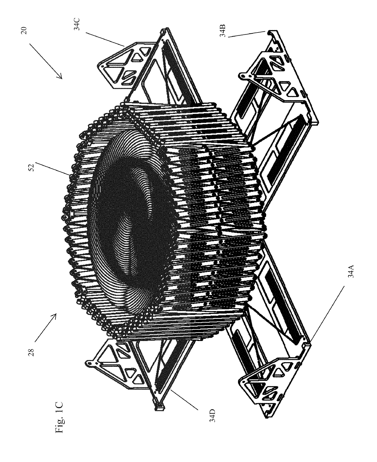
[0031]With reference to FIGS. 1A-1F, an embodiment of a deployable structure 20 for use in establishing a reflectarray antenna (hereinafter referred to as “the deployable structure 20”) is described. The deployable structure 20 conforms to a design specification which requires the deployable structure 20, in the undeployed state, to fit within a volume that is 20 cm×20 cm×25 cm. Additionally, the deployable structure 20 is required to have a mass of no more than 4 kg. Although the deployable structure 20 conforms to the design specification, it should be appreciated that adaptation to other form factors and mass requirements is feasible.

[0032]Generally, the deployable structure 20 includes a canister 22, a feed antenna 24, a flexible reflectarray 26, and a deployment mechanism 28.

[0033]With reference to FIGS. 1A-1E, the canister 22 serves to store the feed antenna 24, flexible reflectarray 26, and the deployment mechanism 28 in an undeployed state and provides a base for supporting ...


PUM


Abstract

A deployable structure for use in establishing a reflectarray antenna is provided that includes a flexible reflectarray and a deployment structure that includes an endless pantograph for deploying the flexible reflectarray from a folded, undeployed state towards a deployed state in which the flexible reflectarray is substantially planar. In a particular embodiment, the deployment structure includes a plurality of tapes that engage the endless pantograph and are used to establish a positional relationship between the deployed reflectarray and another component of the reflectarray antenna.

Description

CROSS-REFERENCE TO RELATED APPLICATIONS[0001]This application claims the priority benefit of U.S. Provisional Patent Application No. 62 / 233,115, filed on Sep. 25, 2015, which application is incorporated by reference into this application in its entirety.FIELD OF THE INVENTION[0002]The invention relates to a deployable structure and, more specifically, to a deployable structure for use in establishing a reflectarray antenna.BACKGROUND OF THE INVENTION[0003]In applications requiring a high-gain antenna, there are at least three types of antennas that are typically employed, namely, a parabolic antenna, phased-array antenna, and a reflectarray antenna. The basic parabolic antenna includes a parabolic shaped reflector and a feed antenna located at the focus of the paraboloid and directed towards the reflector. The phased-array antenna includes multiple antennas with a feed network that provides a common signal to each of the antennas but with the relative phase of the common signal bein...

Claims


Application Information

Patent Timeline
Patent Type & Authority Patents(United States)
IPC IPC(8): H01Q1/08H01Q1/28H01Q3/46H01Q15/14
CPCH01Q1/08H01Q1/28H01Q3/46H01Q1/288H01Q15/14B64G1/222H01Q1/1235H01Q15/161B64G1/407B64G1/443B64G1/66
Inventor HARVEY, THOMAS J.HARVEY, TOBY J.WIENS, MITCHELL T.BAILEY, MARK A.STAMM, SHANE E.PELZMANN, CHRISTOPHER A.
Owner M M A DESIGN
Why Eureka
Try Eureka