Dual cone spray nozzle assembly for high temperature attemperators

a technology of attemperator and nozzle, which is applied in the direction of superheating control, superheating superheaters, lighting and heating apparatus, etc., can solve the problem of insufficient fluid pressure level in the fluid chamber

Active Publication Date: 2019-05-14
CCI ITAL SRL
View PDF83 Cites 0 Cited by
  • Summary
  • Abstract
  • Description
  • Claims
  • Application Information

AI Technical Summary

Benefits of technology

[0013]In accordance with a first embodiment of the present invention, the spray nozzle sub-assembly of the spray nozzle assembly comprises a fixed nozzle element which is integrated into a spring-loaded nozzle element. The fixed nozzle element works in concert with the spring-loaded nozzle element to provide better control over droplet size at low flow / low pressure drop conditions. In addition, such spray nozzle sub-assembly is adapted to improve water droplet fractionation at higher flow rates while further providing an effectively higher spray area through the formation of two water cones (rather than a single water cone) as mentioned above. In this embodiment, the spring-loaded nozzle element comprises a nozzle cone, and an elongate stem which is integrally connected to the nozzle cone and extends axially therefrom. The nozzle cone has a tapered outer surface. The stem is advanced through the central bore of the nozzle housing. The fixed nozzle element is disposed within the nozzle cone of the spring-loaded nozzle element, and fluidly communicates within one or more flow passages formed within the nozzle cone.
[0015]In the spray nozzle assembly including the spray nozzle sub-assembly of the first embodiment, cooling water is introduced into each of the flow passage sections at the first end of the nozzle housing, and thereafter flows therethrough into the fluid chamber. When the spring-loaded nozzle element is in its closed position, a portion of the outer surface of the nozzle cone thereof is seated against the seating surface defined by the nozzle housing, thereby blocking the flow of fluid out of the fluid chamber and hence the spray nozzle assembly. An increase of the pressure of the fluid beyond a prescribed threshold effectively overcomes the biasing force exerted by the biasing spring, thus facilitating the actuation of the spring-loaded nozzle element from its closed position to its open position. When the spring-loaded nozzle element is in its open position, the nozzle cone thereof and the that portion of the nozzle housing defining the seating surface collectively define an annular outflow opening between the fluid chamber and the exterior of the nozzle assembly. The shape of the outflow opening, coupled with the shape of the nozzle cone of the spring-loaded nozzle element, effectively imparts an outer conical spray pattern of small droplet size to fluid flowing from the spray nozzle assembly between the nozzle cone and the nozzle housing. At the same time, fluid flows through the flow passage(s) formed in the nozzle cone to and through the fixed nozzle element as facilitates the formation of an inner conical spray pattern of small droplet size which is concentrically positioned within the outer conical spray pattern. A fluid pressure level within the fluid chamber which is insufficient to overcome the biasing force exerted by the biasing spring as needed to facilitate the actuation of the spring-loaded nozzle element to its open position is likewise insufficient to facilitate the generation of the inner conical spray pattern from the fixed nozzle element despite the flow of fluid thereto via the flow passages within the nozzle cone of the spring-loaded nozzle element. Further, with the biasing spring being captured between the first end of the nozzle housing and the nozzle shield and disposed within the interior of the nozzle shield, such biasing spring is effectively shielded or protected from any directly impingement from fluid flowing through the spray nozzle assembly.
[0018]Fluid flowing into the fluid chamber from the flow passage sections of the nozzle housing is able to reach the outer surface of the nozzle cone of the secondary nozzle element by flowing through openings within the stem of the primary nozzle element as defined by the formation of the spring portion therein. An increase of the pressure of the fluid beyond a first prescribed threshold effectively overcomes the biasing force exerted by the biasing spring portion of the stem of the secondary nozzle element, thus facilitating the actuation thereof from its closed position to its open position relative to the primary nozzle element. When the secondary nozzle element is in its open position, the nozzle cone thereof and that portion of the nozzle cone of the primary nozzle element defining the complimentary seating surface collectively define an annular outflow opening. The shape of the outflow opening, coupled with the shape of the nozzle cone of the secondary nozzle element, effectively imparts an inner conical spray pattern of small droplet size to fluid flowing from the spray nozzle assembly between the nozzle cones of the primary and secondary nozzle elements of the spray nozzle sub-assembly. An increase of the pressure of the fluid beyond a second prescribed threshold effectively overcomes the biasing force exerted by the biasing spring portion of the stem of the primary nozzle element, thus facilitating the actuation thereof from its closed position to its open position relative to the nozzle housing. When the primary nozzle element is in its open position, the nozzle cone thereof and the that portion of the nozzle housing defining the seating surface collectively define an annular outflow opening between the fluid chamber and the exterior of the nozzle assembly. The shape of this outflow opening, coupled with the shape of the nozzle cone of the primary nozzle element, effectively imparts an outer conical spray pattern of small droplet size to fluid flowing from the spray nozzle assembly between the nozzle cone and the nozzle housing.

Problems solved by technology

A fluid pressure level within the fluid chamber which is insufficient to overcome the biasing force exerted by the biasing spring as needed to facilitate the actuation of the spring-loaded nozzle element to its open position is likewise insufficient to facilitate the generation of the inner conical spray pattern from the fixed nozzle element despite the flow of fluid thereto via the flow passages within the nozzle cone of the spring-loaded nozzle element.

Method used


Image

  • Dual cone spray nozzle assembly for high temperature attemperators
  • Dual cone spray nozzle assembly for high temperature attemperators
  • Dual cone spray nozzle assembly for high temperature attemperators

Examples


first embodiment

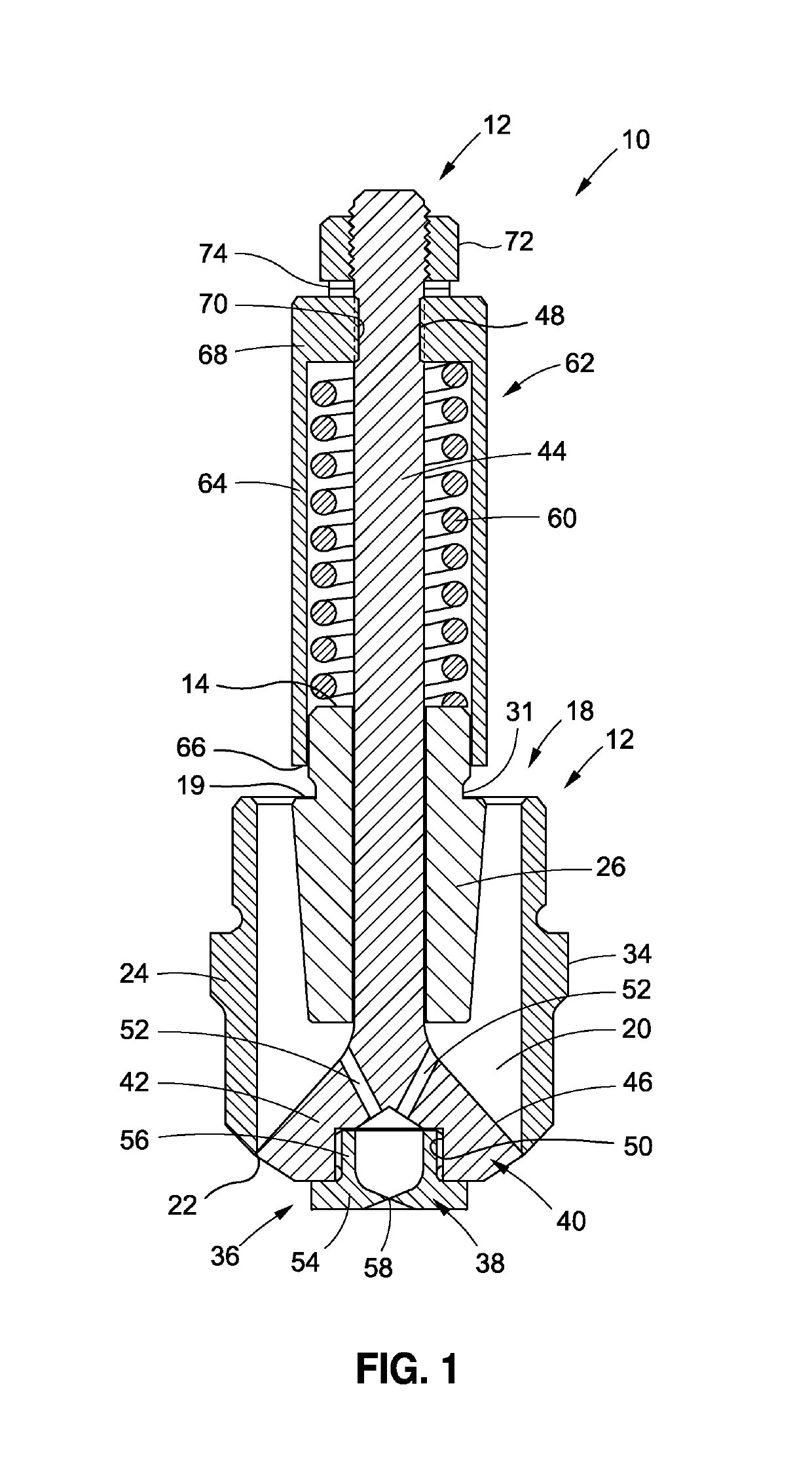
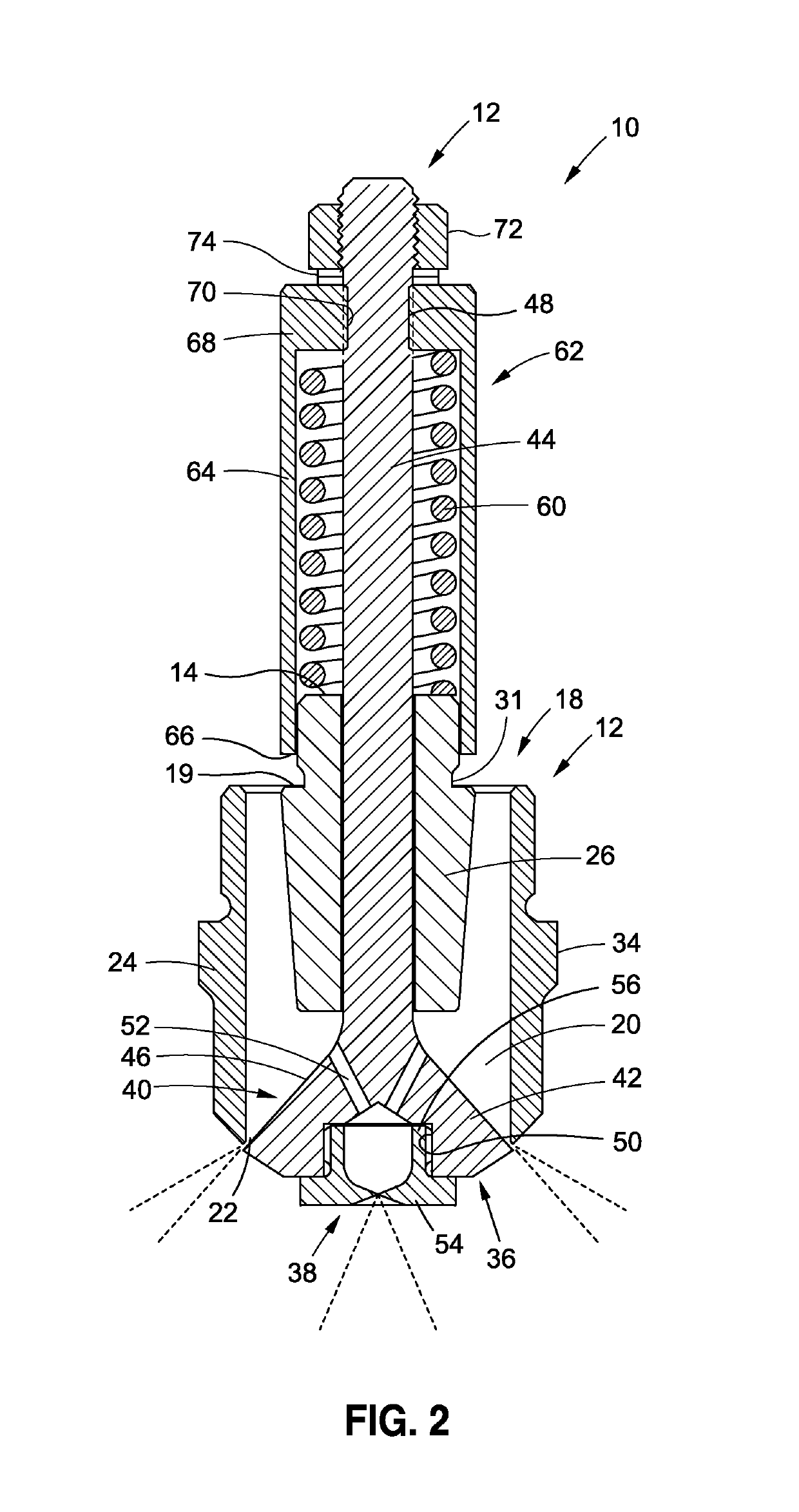
[0030]Referring now to the drawings wherein the showings are for purposes of illustrating preferred embodiments of the present invention only, and not for purposes of limiting the same, FIGS. 1-3 depict a spray nozzle assembly 10 which is outfitted with a spray nozzle sub-assembly 36 constructed in accordance with present invention. In FIG. 1, the spray nozzle sub-assembly 36 is shown in a closed or off position. In FIG. 2, the spray nozzle sub-assembly 36 is shown in an open or on position. The nozzle assembly 10 is adapted for integration into a desuperheating device such as, but not necessarily limited to, a probe type attemperator.

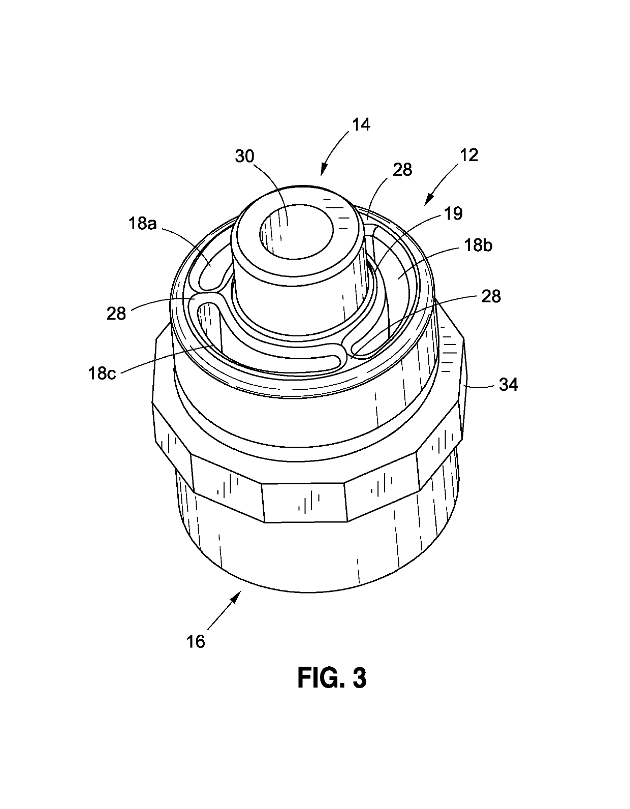
[0031]The nozzle assembly 10 comprises a nozzle housing 12 which is shown with particularity in FIG. 3. The nozzle housing 12 has a generally cylindrical configuration and, when viewed from the perspective shown in FIG. 3, defines a first, top end 14 and an opposed second, bottom end 16. The nozzle housing 12 further defines a generally annular flow pa...

second embodiment

[0051]Referring now to FIGS. 4-8, there is shown a spray nozzle assembly 100 which is outfitted with a spray nozzle sub-assembly 136 constructed in accordance with present invention. In FIG. 4, the spray nozzle sub-assembly 136 is shown in a closed or off position. In FIG. 3, the spray nozzle sub-assembly 136 is shown in a partially open or on position. In FIG. 4, the spray nozzle sub-assembly 36 is shown in a fully open or on position. The nozzle assembly 100 is also adapted for integration into a desuperheating device such as, but not necessarily limited to, a probe type attemperator.

[0052]The nozzle assembly 100 comprises a nozzle housing 112. The nozzle housing 2 has a generally cylindrical configuration and, when viewed from the perspective shown in FIGS. 4-6, defines a first, top end 114 and an opposed second, bottom end 116. The nozzle housing 112 further defines a generally annular flow passage 118. The flow passage 118 preferably comprises two or more arcuate flow passage s...


PUM


Abstract

A spray nozzle assembly for a steam desuperheating or attemperator device. In one embodiment, the spray nozzle sub-assembly of the spray nozzle assembly comprises a fixed nozzle element which is integrated into a spring-loaded nozzle element, and is specifically adapted to improve water droplet fractionation at higher flow rates while further providing an effectively higher spray area through the formation of two water cones (rather than a single water cone), such water cones being sprayed into a flow of superheated steam in order to reduce the temperature of the steam. In another embodiment, the spray nozzle sub-assembly of the spray nozzle assembly comprises a nested pair of spring-loaded primary and secondary nozzle elements which are also adapted to provide an effectively higher spray area through the formation of two water cones.

Description

CROSS-REFERENCE TO RELATED APPLICATIONS[0001]The present application claims priority to U.S. Provisional Application Ser. No. 62 / 032,786 entitled DUAL CONE SPRAY NOZZLE ASSEMBLY FOR HIGH TEMPERATURE ATTEMPERATORS filed Aug. 4, 2014.STATEMENT RE: FEDERALLY SPONSORED RESEARCH / DEVELOPMENT[0002]Not ApplicableBACKGROUND OF THE INVENTION[0003]1. Field of the Invention[0004]The present invention pertains generally to steam desuperheaters or attemperators and, more particularly, to a uniquely configured spray nozzle assembly for a steam desuperheating or attemperator device is, the spray nozzle assembly being adapted to improve the atomization performance of the nozzle at very low flow rates. In one embodiment, the spray nozzle sub-assembly of the spray nozzle assembly comprises a fixed nozzle element which is integrated into a spring-loaded nozzle element. The spray nozzle sub-assembly is specifically adapted to improve water droplet fractionation at lower flow rates through the use of onl...

Claims


Application Information

Patent Timeline
Patent Type & Authority Patents(United States)
IPC IPC(8): F22G5/12B05B1/14B05B1/30B05B1/32B05B1/06B05B1/02
CPCF22G5/123B05B1/14B05B1/3066B05B1/323B05B1/3073B05B1/06B05B1/02
Inventor GIOVE, FABIO
Owner CCI ITAL SRL
Why Eureka
Try Eureka