Brushless direct current motor with integrated fan

a direct current motor and integrated fan technology, which is applied in the direction of rotating magnets, synchronous machines with stationary armatures, stator/rotor bodies, etc., can solve the problems of time-consuming and difficult current methods for attaching magnets to the rotors, and achieve the effect of reducing drag of rotating components, improving airflow efficiency, and improving airflow

Active Publication Date: 2019-05-14
SFEG CORP
View PDF24 Cites 2 Cited by
  • Summary
  • Abstract
  • Description
  • Claims
  • Application Information

AI Technical Summary

Benefits of technology

[0022]According to further embodiments of the rotor assembly, the fan blades have an airfoil shape to improve efficiency of air flow by reducing drag of the rotating components at low and high speeds and to provide increased airflow to cool the motor.

Problems solved by technology

With respect to the manufacture of BLDC motors, the current method for attaching magnets within the rotor is difficult and time consuming as the magnets must be evenly spaced and glued into position with a special handheld tool.
Another disadvantage of current brushless direct current motor designs is that the fans which are used to cool the motor are positioned relatively far away from the rotor and stator assembly.

Method used


Image

  • Brushless direct current motor with integrated fan
  • Brushless direct current motor with integrated fan
  • Brushless direct current motor with integrated fan

Examples


Embodiment Construction

[0036]Brushless direct current motors are used in OEM equipment for consumer use in blenders, vacuum cleaners, air compressors, blowers (high speed), large scale printers, hospital beds, and other small powered consumer and industrial devices.

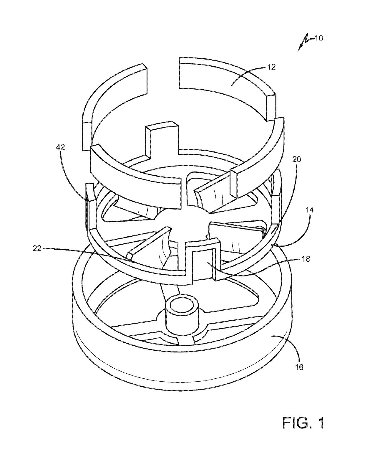
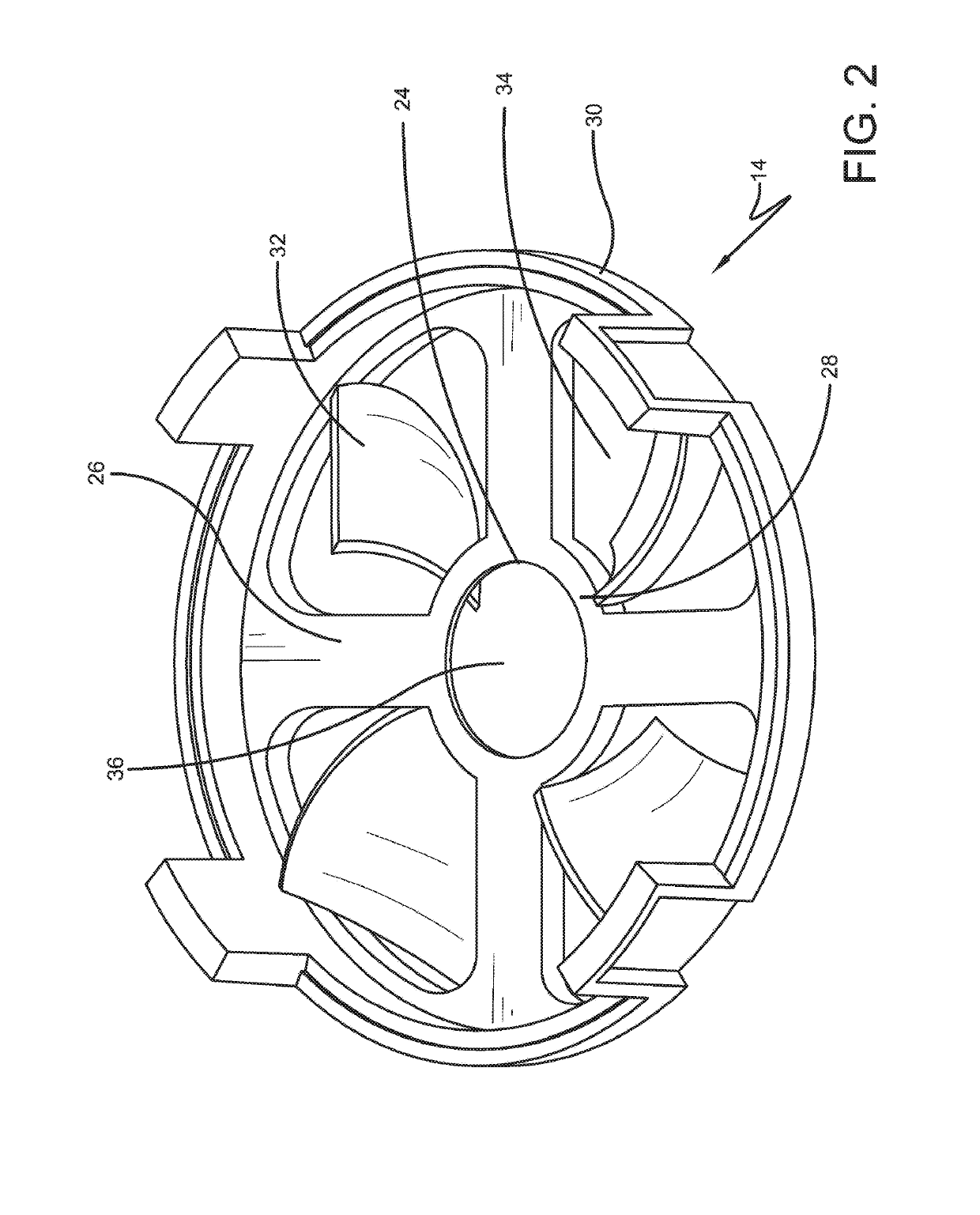
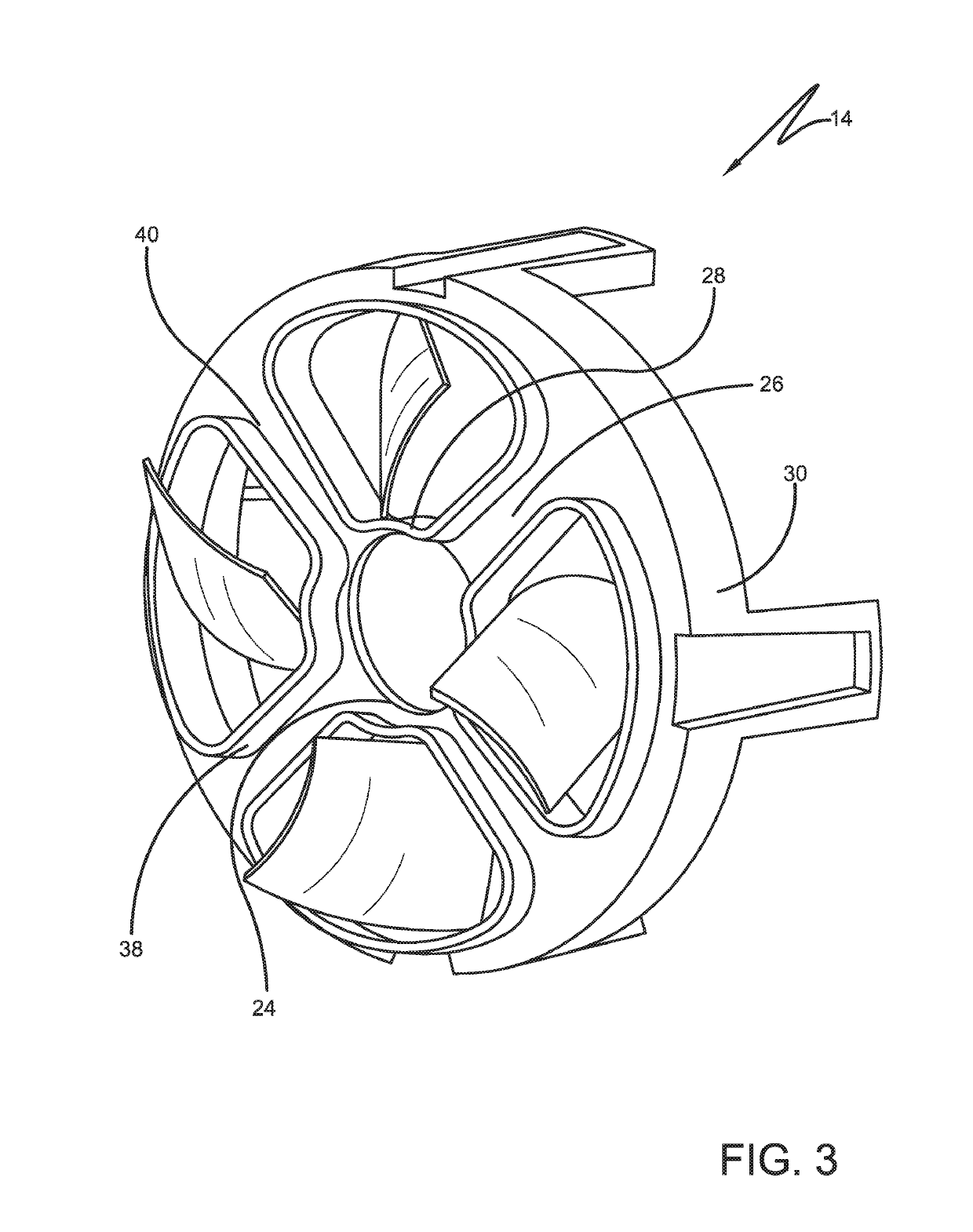
[0037]The present disclosure relates to a rotor assembly for a brushless direct current motor. In addition, the present disclosure also relates to a brushless direct current motor assembly, a method of assembling a rotor assembly for a brushless direct current motor, a method of assembling a brushless direct current motor and a method of operating a brushless direct current motor. The rotor assembly (also referred to as a magnet cup assembly) includes an insert which is positioned within an outer rotor cup for a brushless direct current (DC) motor. The insert may be formed from a plastic material although in certain embodiments, it is also possible to form the insert from other materials including various types of metals. The outer rotor cup ma...


PUM


Abstract

Provided is a rotor assembly for a brushless direct current motor. The rotor assembly includes an insert which fits within an outer rotor cup. The insert locates the position of the magnets and secures them with extended features. Curved fan blades are integrated into the insert to provide improved airflow and cooling during rotation. The insert has features incorporated to reduce overall noise caused by air flow by having smooth transitions between mating surfaces and joints. A trench is incorporated within the insert to provide an overflow catch for excess adhesive when the magnet segments are “glued” into place.

Description

I. BACKGROUNDA. Technical Field[0001]The present disclosure generally relates to a brushless direct current motor assembly which is designed for use in various types of small motor applications.B. Description of Related Art[0002]Direct current (DC) motors typically include a stator which provides a constant magnetic field and a rotating armature which constitutes a series of electrical coils. A permanent magnet stator pole is used for small DC motors. For larger motors, an electromagnet is used for the stator with the field coil of the electro-magnet being powered from the same DC power source that is used to power the armature. The armature is connected to a direct current power source (e.g., a battery) through a pair of commutator rings. Spring loaded commutator brushes are used to maintain contact between the commutator and the power source. The power source provides a direct current through the armature or coil. This electrical current imparts an electromotive force on the armat...

Claims


Application Information

Patent Timeline
Patent Type & Authority Patents(United States)
IPC IPC(8): H02K9/06H02K15/03H02K21/14H02K15/16
CPCH02K9/06H02K21/14H02K15/165H02K15/03H02K1/2791
Inventor HOLMAN, STEVEN J.
Owner SFEG CORP
Why Eureka
Try Eureka