Device and system for quantifying the useful thermal energy available in a tank
Active Publication Date: 2019-05-21
CENT NAT DE LA RECHERCHE SCI
View PDF13 Cites 1 Cited by
Summary
Abstract
Description
Claims
Application Information
AI Technical Summary
This helps you quickly interpret patents by identifying the three key elements:
Problems solved by technology
Method used
Benefits of technology
Benefits of technology
This patent provides a device for measuring the useful thermal energy in a tank. The device uses thermoelectric converters to convert the heat into electrical energy, which can be used to provide useful work. The device includes an electrical temperature sensor that is sensitive to a specific temperature threshold, making it easy and inexpensive to implement. Additionally, the device includes a thermistor to further quantify the thermal energy in the tank. The electrical resistance of each thermoelectric converter is also designed to have a specific value that facilitates the conversion of the thermal energy to electrical energy. Overall, this device provides a simple and cost-effective solution for measuring the useful thermal energy in a tank.
Problems solved by technology
Furthermore, a sufficient number of electrical temperature sensors have to be provided in order to obtain a precise measurement, which renders even more complex the processing of the multiple electrical signals resulting from the measurements.
Method used
Image
Click on the blue label to locate the original text in one second.
Reading with bidirectional positioning of images and text.
Examples
first embodiment
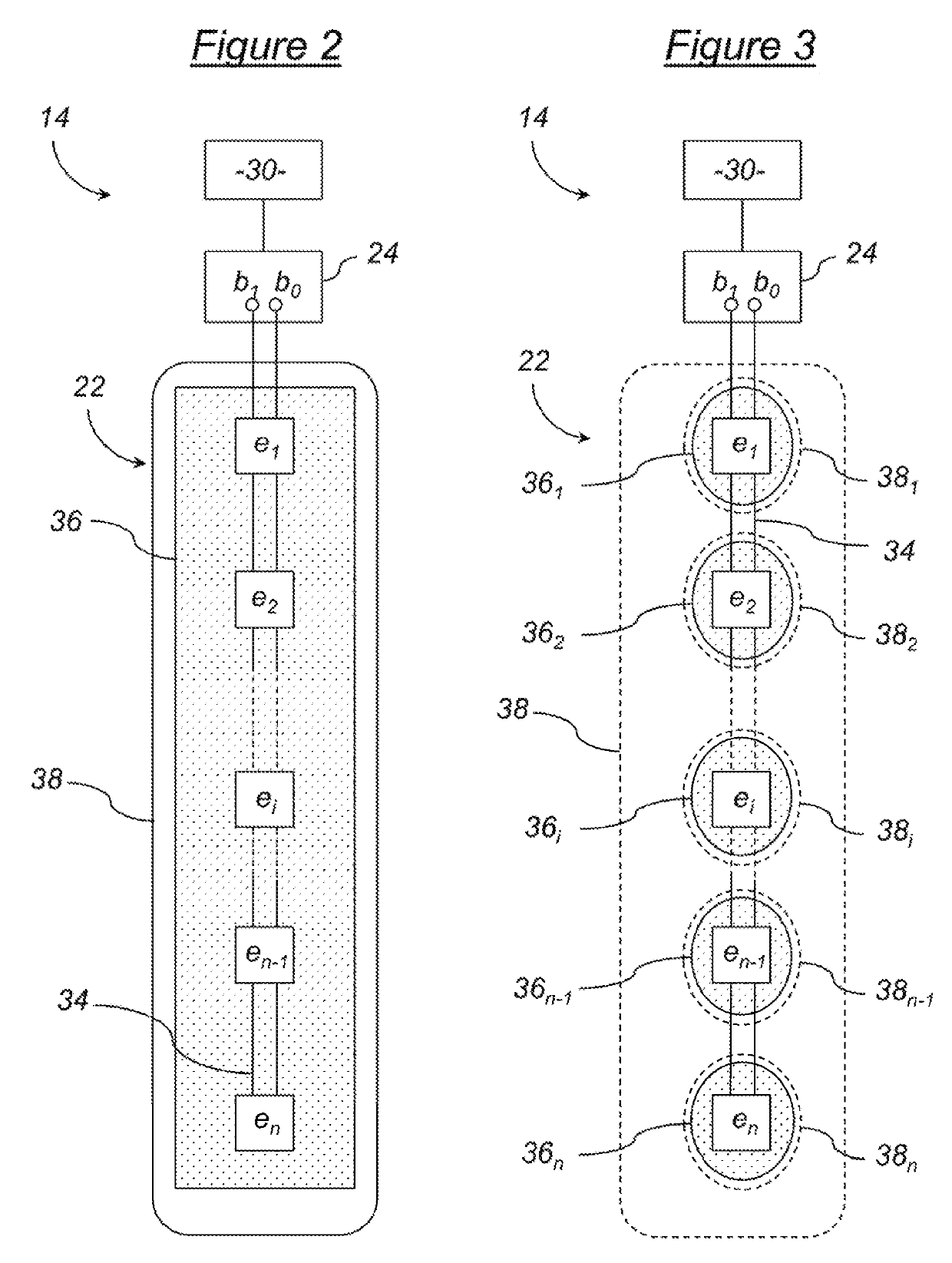
[0057]According to this first embodiment, the device 14 for quantifying useful heat further includes a single support 36, in the shape of a rectangular plate, that supports but also thermally and electrically insulates the thermoelectric converters e1, e2, . . . , ei, . . . , en-1, en between them. According to an alternative embodiment, this single support 36 can be comprised of a thin plate made of a semiconductor material, but in other alternative embodiments it could be carried out with other thermally and electrically insulating materials. The thermoelectric converts e1, e2, . . . , ei, . . . , en-1, en and the electric circuit 34 can be simply glued or, according to the manufacturing process, printed on the single support 36. They as such form a single module that cannot be divided.
[0058]According to this first embodiment also, the module that cannot be divided formed of the single support 36, thermoelectric converters e1, e2, . . . , ei, . . . , en-1, en and of the electric c...
second embodiment
[0067]The originality of this second embodiment of the device for quantification 14 is due to the fact that a unit comprising a thermoelectric converter, for example ei, and its corresponding independent support, 36i, constitutes an independent module.
[0068]These n independent modules are then connected together by the electric circuit 34, for example using two connector wires such as shown in FIG. 3.
[0069]According to a first alternative of this second embodiment of the device for quantification 12, the independent modules connected together by the electric circuit 34 can then be arranged in the protective coating 38 in a way substantially equivalent to the first embodiment.
[0070]According to a second alternative of this second embodiment of the device for quantification 12, the protective coating 38 can be replaced with n independent protective coatings 381, 382, . . . , 36i, . . . 38n-1, 38n, for example made of PTFE also, wherein the n independent modules can be respectively arr...
PUM
Abstract
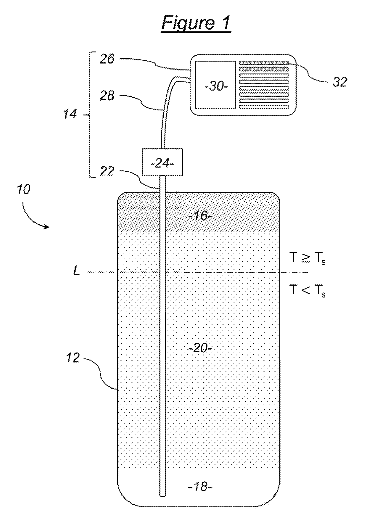
A device for quantifying a useful thermal energy available in a tank for storing a heated or cooled fluid or solid includes: a plurality of thermoelectric converters configured to be distributed in plural locations of the storage tank; an electric circuit interconnecting the thermoelectric converters; a device measuring a single electrical variable of the electric circuit; and a converter converting a single measurement of the single electrical variable into a value for quantification of the useful thermal energy available in the storage tank.
Description
BACKGROUND[0001]This invention relates to a device for quantifying a useful thermal energy available in a tank for storing a heated or cooled fluid or solid. It also relates to a system for quantifying useful thermal energy comprising such a device.[0002]A tank for storing a heated fluid or solid is generally used in systems for generating, storing and restoring heat. Likewise, a tank for storing a cooled fluid or solid is generally used in systems for generating, storing and restoring cold.[0003]More concretely, a simple and common example of application consists in using a storage tank of heated water in a system for generating and for consuming sanitary hot water or water for heating. In such a storage tank, hot and cold water cohabitate and tend to remain gradually separated into horizontal strata or isotherms in each one of which the water substantially has the same temperature. But from one stratum to the other, the temperature of the water differs, with the strata of hot wate...
Claims
Application Information
Patent Timeline
Application Date:The date an application was filed.
Publication Date:The date a patent or application was officially published.
First Publication Date:The earliest publication date of a patent with the same application number.
Issue Date:Publication date of the patent grant document.
PCT Entry Date:The Entry date of PCT National Phase.
Estimated Expiry Date:The statutory expiry date of a patent right according to the Patent Law, and it is the longest term of protection that the patent right can achieve without the termination of the patent right due to other reasons(Term extension factor has been taken into account ).
Invalid Date:Actual expiry date is based on effective date or publication date of legal transaction data of invalid patent.

