Static discharger and aircraft having the static discharger

a technology of static discharger and static discharger, which is applied in the installation of lighting conductors, cleaning processes and apparatuses, and electric cable installations, etc. it can solve the problems of increased weight, inconvenient installation, and complex installation, so as to avoid the impact of aerodynamic surface, increase the weight, and increase the universality of the static discharger

Active Publication Date: 2019-05-28
AIRBUS BEIJING ENG CENT
View PDF6 Cites 0 Cited by
  • Summary
  • Abstract
  • Description
  • Claims
  • Application Information

AI Technical Summary

Benefits of technology

[0014]Another object of the present application is to provide a static discharger with which a basement and then the whole static discharger can be flexibly adapted to a trailing edge profile member which is relatively narrow.
[0046]In addition, according to the present application, since no additional installation member such as a metallic plate is needed in the installation of the static discharger, disadvantageous circumstances such as that the weight is increased, the assembly is complex and the aerodynamic surface is affected can be avoided. Besides, the so called suspended installation manner or bestriding installation manner can be avoided since generally the basement can be completely superposed on the Bat trailing edge profile member, thus the electrical contact can be improved, the installation course can be further simplified and the affection on the aerodynamic surface can be further reduced.

Problems solved by technology

In addition, the partially suspended installations of the metallic plate 30A and the basement 12A may also affect the aerodynamic surface (which will cause turbulence effect) and cause inconvenient installation.
In this way, in the static discharger 10B according to the relevant technology, similarly, since an additional metallic plate 30B is needed for the installation, the weight is increased, the installation is complex, and the aerodynamic surface is affected.

Method used


Image

  • Static discharger and aircraft having the static discharger
  • Static discharger and aircraft having the static discharger
  • Static discharger and aircraft having the static discharger

Examples


first embodiment

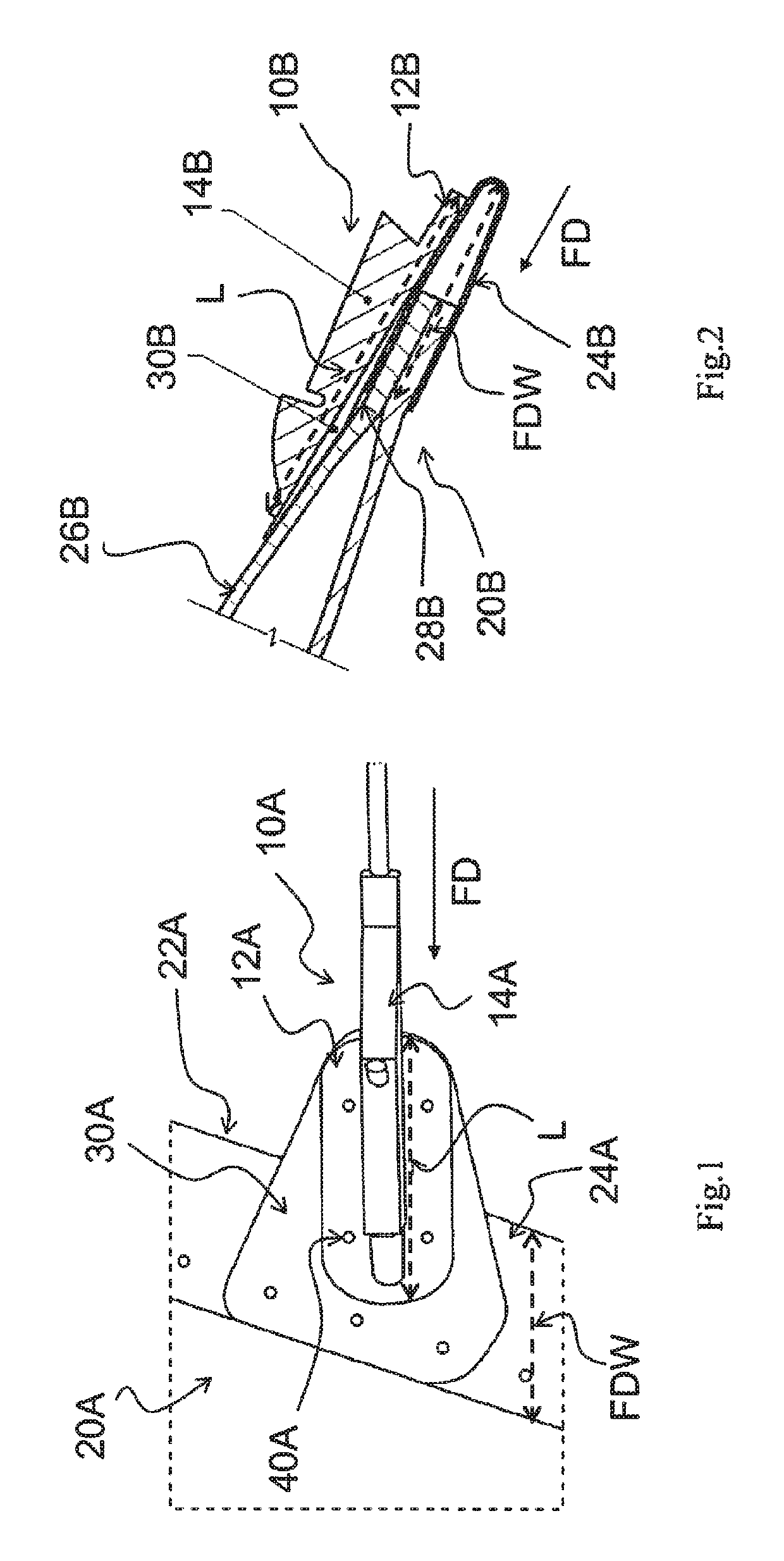
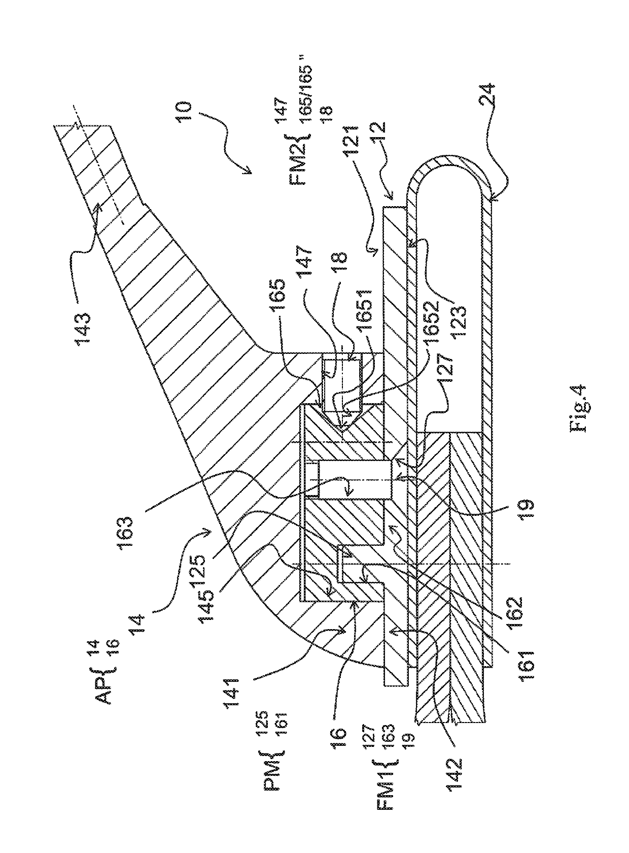
[0067]In some examples, a drilling trajectory line 129 is denoted on at least the upper surface 121 of the basement 12 (referring to FIG. 7 which is a schematic view showing bore arrangement on the basement according to the present application). The drilling trajectory line 129 is a circular arc trajectory (which has a radius R corresponding to a distance D between the shaft hole and a fastening hole of the internal-media 16, which will be described hereinafter) centered on a site C (which corresponds to a center line of the protrusion 125 or a center 161C of the shaft hole 161). As will be described hereinafter, the drilling trajectory line 129 facilities the determination of a position of the bore on the basement 12 to facilitate an accurate assembly / installation of the static discharger 10.

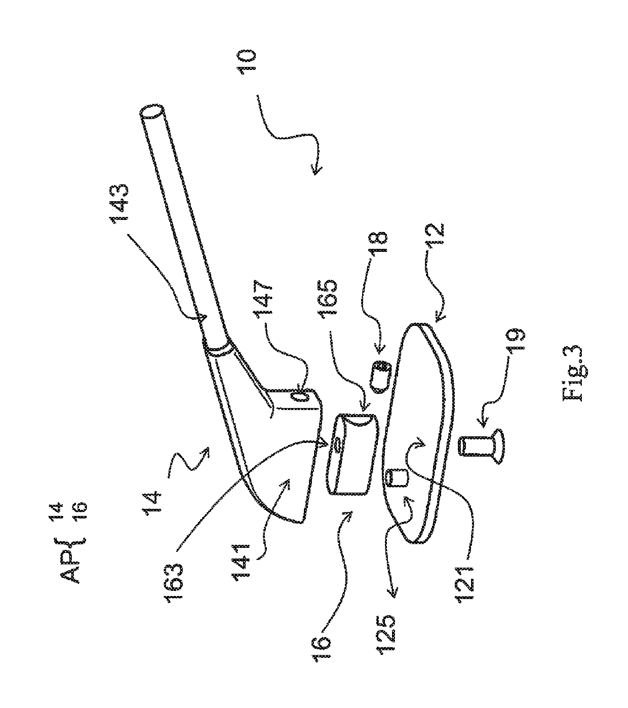
[0068]The discharging portion 14 may include a connection portion 141 and tail portion 143. A receiving groove 145 (referring to FIG. 4 and FIG. 8 which is a perspective view showing the discha...

second embodiment

[0098]In the second embodiment, a (circular) protrusion 125′ protruding upwardly from an upper surface 121′ of a basement 12′ is provided at a substantially central region of the upper surface 121′. Accordingly, a (circular) shaft hole 161′ is formed in a substantially central region of a bottom portion of an internal-media 16′. Herein, it is to be noted that the protrusion 125′ and the shaft hole 161′ together constitute a pivoting mechanism PM′ according to the present application.

[0099]In the second embodiment, two fastening holes (threaded holes) 163′ are respectively formed on front and rear sides of the internal-media 16′ with respect to the shaft hole 161′. In a preferable example, distances from the two fastening holes 163′ to the shaft hole 161′ are equal and are spaced apart at 180 degrees. Accordingly, two corresponding bores (not shown in the figures will be drilled on the circular arc drilling trajectory of the basement 12 on the installation site, and two corresponding...


PUM


Abstract

The present application relates to a static discharger and an aircraft including the static discharger. According to an aspect of the present application, a static discharger is provided which includes: a basement; and a discharger body adapted to be installed to the basement. The static discharger further includes a first fixing mechanism adapted to fix the discharger body to the basement. A pivoting mechanism is provided between the basement and the discharger body, the pivoting mechanism allowing the discharger body to pivot with respect to the basement so as to adjust an installation orientation of the discharger body with respect to the basement during an on-site-installation of the static discharger. According to the present application, for example, installation adaptation and universality of the static discharger can be improved.

Description

RELATED APPLICATIONS[0001]This application claims priority to Chinese Patent Application No. 201520144802.X, filed Mar. 13, 2015, which is incorporated by reference in its entirety herein.FIELD OF THE INVENTION[0002]The present application relates to a static discharger and an aircraft having the same, and more particularly to a static discharger improved in aspects of installation adaptation and universality and so on.BACKGROUND OF THE INVENTION[0003]Generally, high-speed moving bodies such as the airplane, the aerospace plane, the train and the automobile are provided with a static discharger. In particular, the static discharger is an essential component in the airplane used to protect relevant structures of the airplane by discharging the current (static electricity) to the air slowly. The static discharger may be installed at the wing (for example, a trailing edge of the outboard aileron and / or a trailing edge of the winglet), the VTP (vertical fin plane), the HTP (horizontal f...

Claims


Application Information

Patent Timeline
Patent Type & Authority Patents(United States)
IPC IPC(8): B08B6/00B64D45/02H02G13/00
CPCH02G13/00B64D45/02
Inventor HAN, ZENGLISUN, YUMIN
Owner AIRBUS BEIJING ENG CENT
Why Eureka
Try Eureka