
Method and magnetic resonance apparatus for determining absolute receive sensitivity maps for reception coils

a magnetic resonance apparatus and absolute three-dimensional technology, applied in wave based measurement systems, instruments, reradiation, etc., can solve problems such as image artifacts, difficult to discern, and detrimental to a reliable diagnostic assessmen

Active Publication Date: 2019-05-28
SIEMENS HEALTHCARE GMBH
View PDF15 Cites 3 Cited by
  • Summary
  • Abstract
  • Description
  • Claims
  • Application Information

AI Technical Summary

Benefits of technology

The present invention is a method for improving the accuracy of magnetic resonance imaging (MRI) by using tissue-impedance mapping techniques to determine the distribution of electrical properties in the region of interest. This is not dependent on the coil used or the position of the reception coil. The coil-geometry parameters can be determined from the magnetic resonance data or from the position sensors on the coil. The invention also uses numerical simulation techniques to solve the complex electromagnetic interactions. The subject parameters can be determined from magnetic resonance data acquired in a prescan and used to evaluate the impact of the acquisition parameters on the SAR (specific absorption rate) values. The technical effects of the invention include improved accuracy of MRI and better understanding of the electromagnetic properties of the subject under examination.

Problems solved by technology

Inhomogeneities in the magnetic resonance fields used to acquire raw data in a magnetic resonance scanner are a common cause of image artifacts in the magnetic resonance image.
The field inhomogeneities, which result in image inhomogeneities, cause a particular problem when the basic magnetic field (B0 field) has a field strength of at least 3 T. If a subject under examination, in particular a patient, is brought into the magnetic resonance scanner and hence into the basic magnetic field, electrical effects arise that may influence the transmission and reception properties of the RF coils used, and are visible as shading in the reconstructed magnetic resonance datasets.
This shading can conceal the underlying anatomy or make it harder to discern, and is hence detrimental to a reliable diagnostic assessment.
The reason why there is a sharp increase in the image artifacts resulting from inhomogeneities in the RF field (B1 field), produced by the RF coils, at higher basic magnetic field strengths, in particular field strengths of at least 3 T, is that in such strong fields, the wavelengths at the Larmor frequency become comparable to the dimensions of the subject under investigation, in particular a patient, and the electromagnetic properties of human tissue affect the ultimate distribution of the RF fields inside the body, which results in the inhomogeneity side-effects in magnetic resonance imaging.
In the transmit case, the dielectric effects interact at high field strengths to produce an inhomogeneous distribution of the emitted RF power inside the body, which results in erroneous flip angles in the imaging volume and hence in unwanted modulation of the original magnetic resonance signals in the tissue by the sine of the flip angle.
The main obstacle to determining absolute transmit / reception sensitivity maps lies in the interdependence of the transmission sensitivity (described by the B1+ map), the reception sensitivity (described by the B1− map) and the image contrast, as given by the equations known in the prior art.
Such an approach, however, is obviously unsuitable for examining patients in the patient receiving area of a magnetic resonance scanner of a magnetic resonance apparatus.
This immediately results in the problem that all PAT image reconstruction techniques require prior knowledge about the actual receive sensitivities of the reception coils.
Whereas the approach that uses relative reception sensitivity maps for the reception coils may be adequate for suppressing PAT aliasing artifacts caused by undersampling, the disadvantage with this approach is that the reconstructed magnetic resonance image dataset is still modulated by the reception sensitivity of the (possibly virtual) reference coil, which itself suffers from inhomogeneities.
This results in an uneven presentation of the imaged anatomy, i.e.
The dielectric effects in magnetic resonance scanners having basic magnetic field strengths of at least 3 T mean, however, that this assumption is erroneous because even for the whole-body coil, reception sensitivity profiles differ widely between different patients and between different areas of examination.
This is not generally true, however, which means that errors occur not only when the head is not centrally positioned but also when abnormalities are present such as tumors, stenoses or hemorrhages.
In addition, this approach is also subject to further known limitations in the estimate of B1+ maps, namely the need for a number of acquisition processes (scans), which are susceptible to movement, low signal-to-noise ratios and low resolutions.

Method used


Image

  • Method and magnetic resonance apparatus for determining absolute receive sensitivity maps for reception coils
  • Method and magnetic resonance apparatus for determining absolute receive sensitivity maps for reception coils

Examples


Embodiment Construction

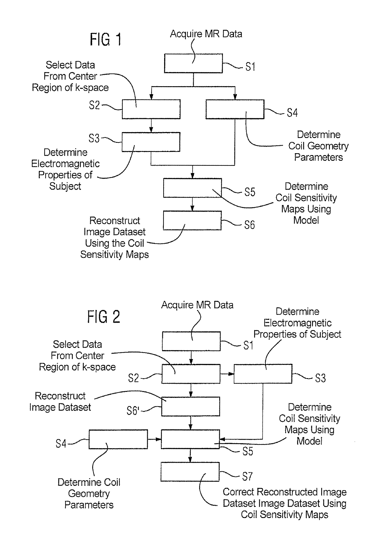
[0047]FIG. 1 shows a flowchart of a first exemplary embodiment of the method according to the invention, as used for improving the reconstruction of magnetic resonance image datasets in accelerated parallel imaging (PAT). In a first, generally known step S1 of this method, magnetic resonance data are acquired that will form the basis of the magnetic resonance image dataset to be reconstructed later. In this process, a region about the center of k-space is fully sampled, whereas undersampling exists outside this region.

[0048]In a step S2, the magnetic resonance data from the fully sampled region about the k-space center (also known as autocalibration lines) are used to determine relative reception sensitivity maps for the number of reception coils used; the reference value used here is the square root of the sum-of-squares of all the individual coil sensitivities (ROOT-SOS).

[0049]In a step S3, the procedure described in the above-cited article by José P. Marques is used to determine ...


PUM


Abstract

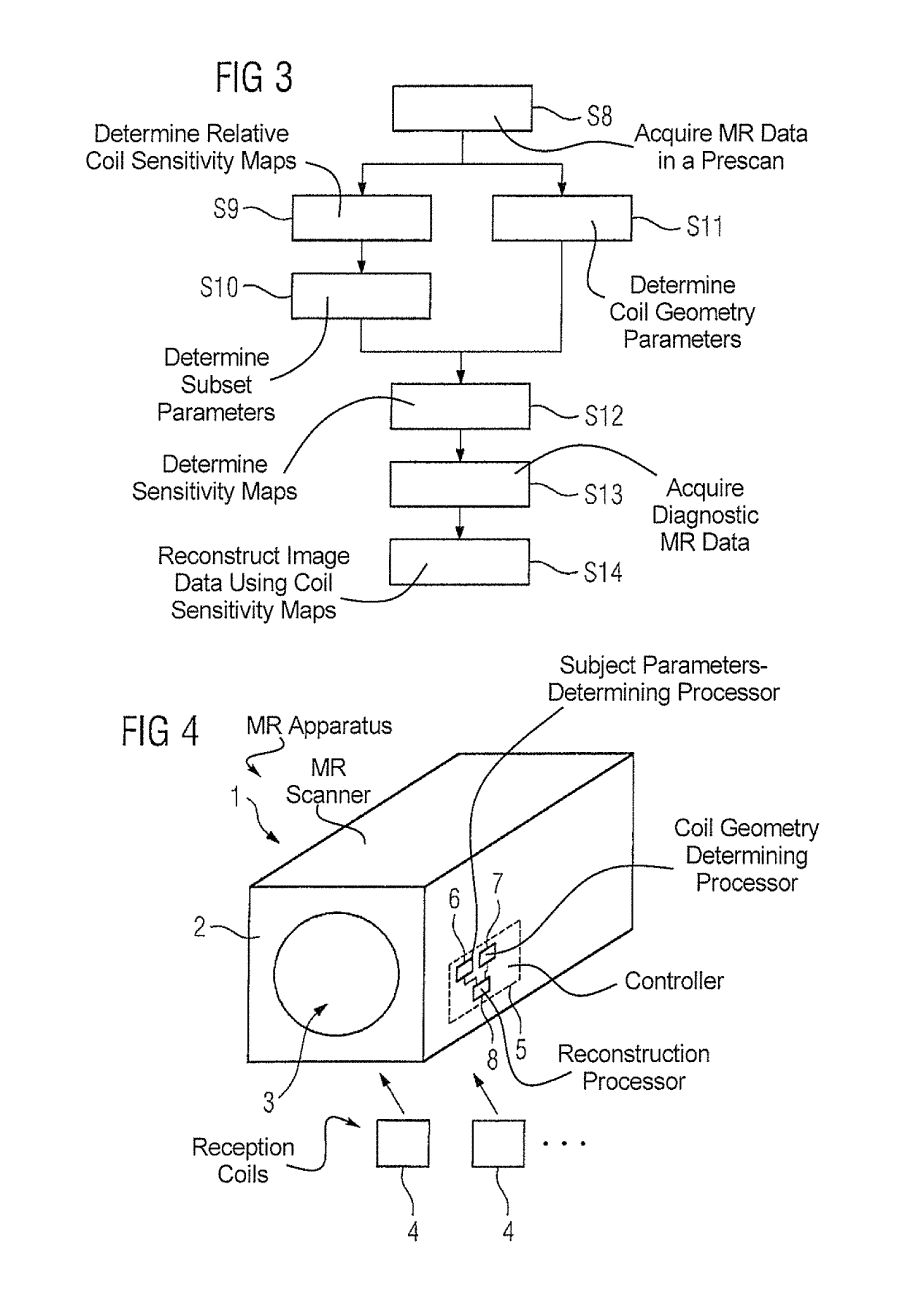
In a method and magnetic resonance apparatus for determining absolute three-dimensional reception sensitivity maps for reception coils in a scanner of the magnetic resonance, in particular a scanner having a basic magnetic field strength of at least 3 T, in the presence of a subject under examination that affects the reception sensitivity, spatially resolved subject parameters are determined, which specify electromagnetic properties of the subject under examination, and coil-geometry parameters are determined, which specify the spatial arrangement of the reception coils in the magnetic resonance scanner. The reception sensitivity maps are determined by simulation in a model specified by the subject parameters and the coil-geometry parameters.

Description

BACKGROUND OF THE INVENTION[0001]Field of the Invention[0002]The invention concerns a method for determining absolute three-dimensional reception sensitivity maps for reception coils in a magnetic resonance apparatus, in particular in a magnetic resonance apparatus having a basic magnetic field strength of at least 3 T, in the presence of a subject under examination that affects the reception sensitivity. The invention also relates to a magnetic resonance apparatus for implementing such a method.[0003]Description of the Prior Art[0004]Inhomogeneities in the magnetic resonance fields used to acquire raw data in a magnetic resonance scanner are a common cause of image artifacts in the magnetic resonance image. The field inhomogeneities, which result in image inhomogeneities, cause a particular problem when the basic magnetic field (B0 field) has a field strength of at least 3 T. If a subject under examination, in particular a patient, is brought into the magnetic resonance scanner and...

Claims


Application Information

Patent Timeline
Patent Type & Authority Patents(United States)
IPC IPC(8): G01V3/00G01R33/24G01R33/561G01R33/565
CPCG01R33/246G01R33/5611G01R33/5659
Inventor POPESCU, STEFAN
Owner SIEMENS HEALTHCARE GMBH
Learn More