Systems and methods for selecting a radiation therapy treatment plan

a radiation therapy and treatment plan technology, applied in the field of modulated radiation therapy, can solve the problems of affecting the quality and efficiency of the treatment plan, and achieve the effects of improving the overall treatment delivery, improving the quality and efficiency of the treatment plan, and ensuring the uniformity of the target dose distribution

Active Publication Date: 2019-06-04
ACCURAY
View PDF4 Cites 27 Cited by
  • Summary
  • Abstract
  • Description
  • Claims
  • Application Information

AI Technical Summary

Benefits of technology

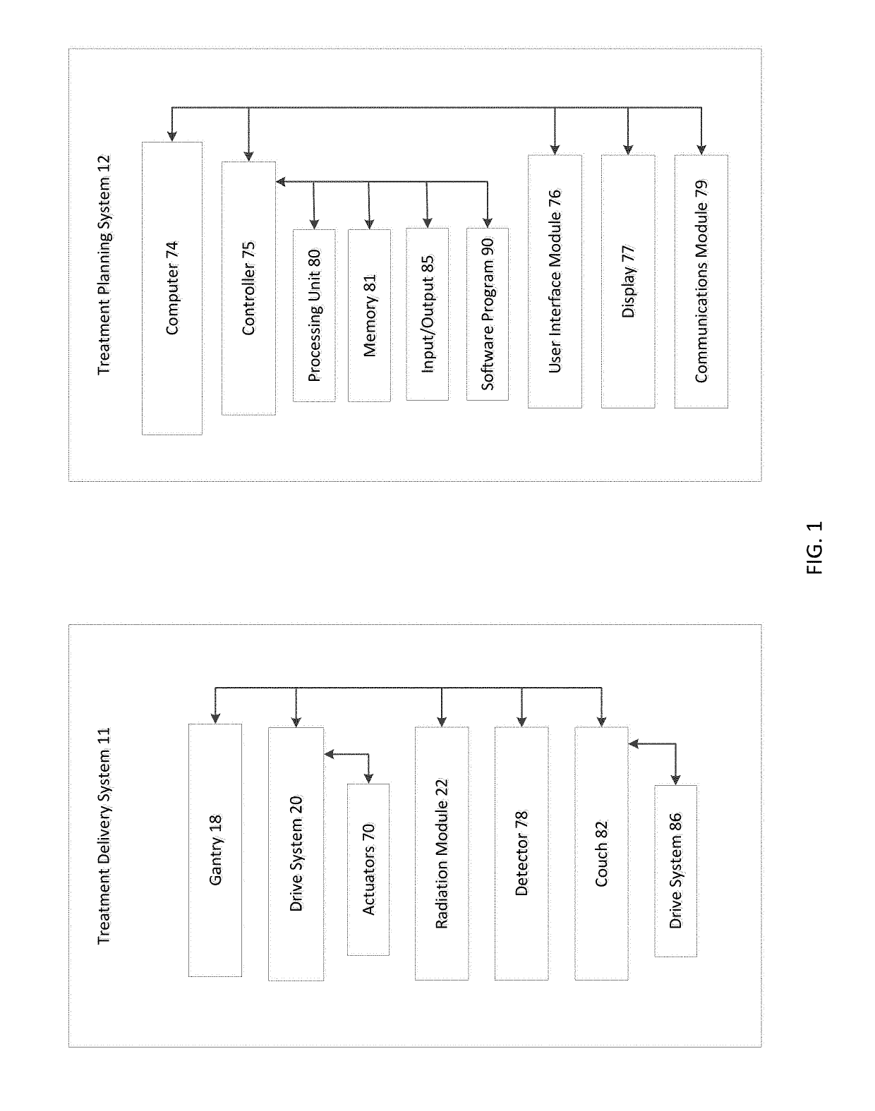
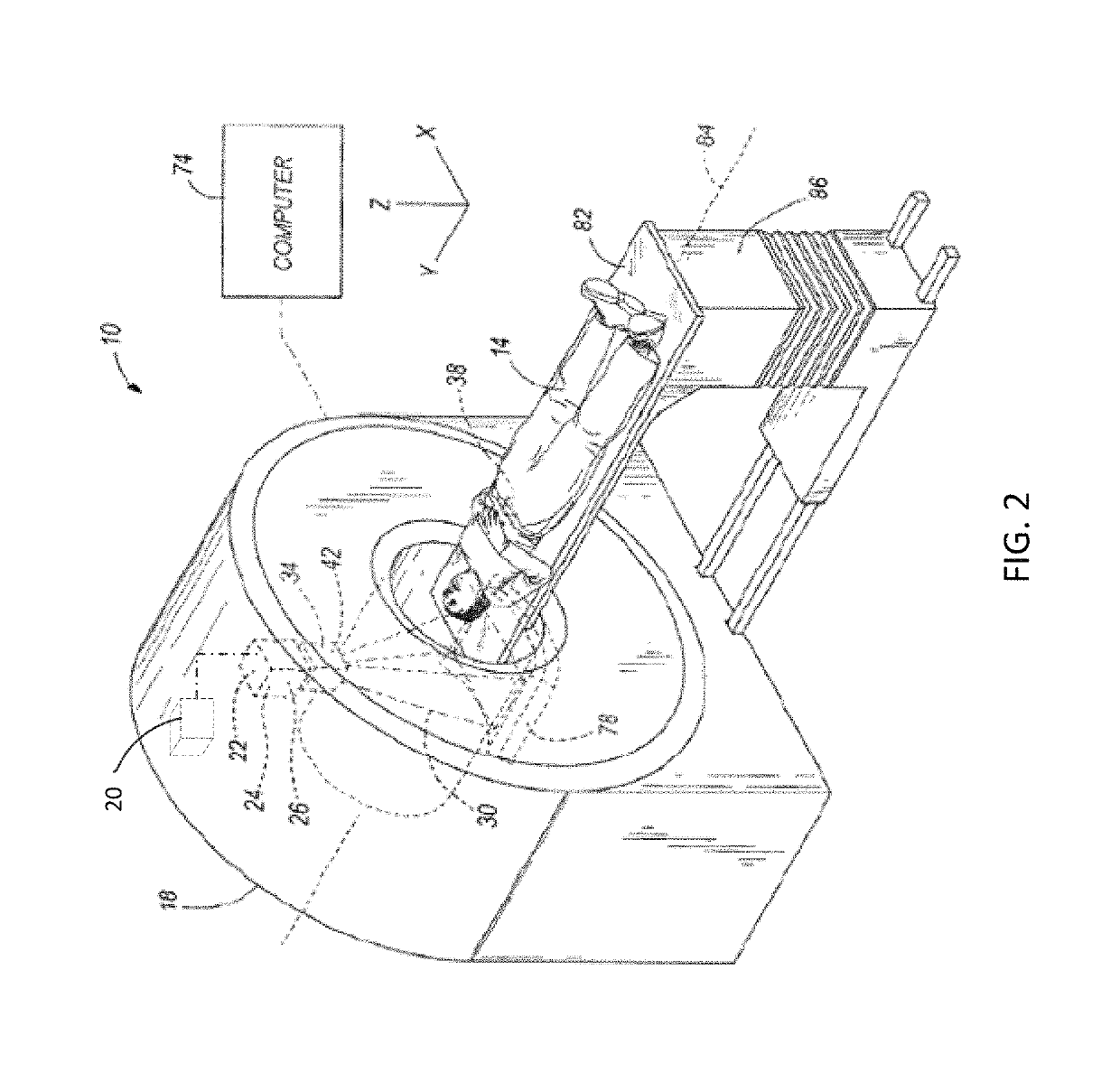
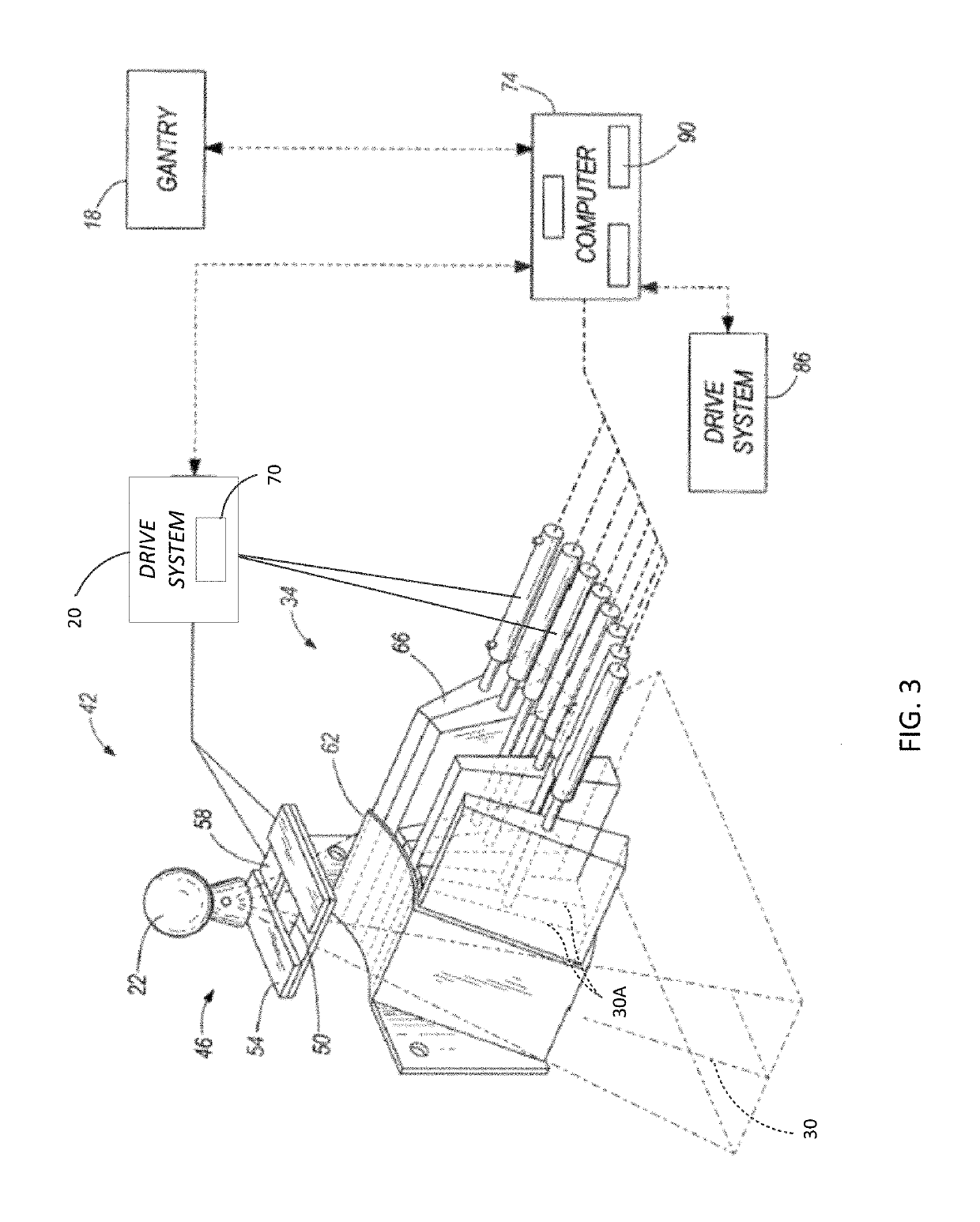
[0006]Once a treatment plan is in place, the treatment plan is executed by and the prescribed radiation is delivered through a treatment delivery system. The treatment delivery system typically includes a couch that supports the patient and a gantry with a radiation source that rotates around the couch to deliver radiation to the tumor from different angles. As the gantry rotates, the couch translates in a linear direction relative to the gantry. Therefore, the radiation delivered from the radiation source on the gantry is delivered along a helical path. The helical delivery path is, in part, characterized by its pitch, which is a measure of the distance that the couch moves during one gantry rotation. Studies have shown that the pitch of the helical path created by the rotating gantry and the translating couch greatly affects the uniformity of the target dose distribution, and hence the quality and the efficiency of the treatment plan. However, there are some difficulties in choosing a pitch that is appropriate for the treatment. Accordingly, optimization of the pitch during the treatment planning phase can improve the overall treatment delivery.

Problems solved by technology

Furthermore, the manner in which the radiation is delivered (e.g., angle, intensity, duration) can affect the quality and efficiency of the treatment plan.

Method used


Image

  • Systems and methods for selecting a radiation therapy treatment plan
  • Systems and methods for selecting a radiation therapy treatment plan
  • Systems and methods for selecting a radiation therapy treatment plan

Examples


Embodiment Construction

[0020]Before any embodiments of the invention are explained in detail, it is to be understood that the invention is not limited in its application to the details of construction and the arrangement of components set forth in the following description or illustrated in the following drawings. The invention is capable of other embodiments and of being practiced or of being carried out in various ways. Also, it is to be understood that the phraseology and terminology used herein is for the purpose of description and should not be regarded as limiting. The use of “including,”“comprising,” or “having” and variations thereof herein is meant to encompass the items listed thereafter and equivalents thereof as well as additional items. Unless specified or limited otherwise, the terms “mounted,”“connected,”“supported,” and “coupled” and variations thereof are used broadly and encompass both direct and indirect mountings, connections, supports, and couplings. The use terms “optimize,”“optimiza...


PUM


Abstract

A method of selecting a radiation therapy treatment plan for a patient. The treatment plan is implemented through a radiation delivery system including a gantry capable of rotating around a couch, in which the couch is movable in a linear direction relative to the gantry. The movement of the couch and the gantry creates a helical delivery path having a pitch. A radiation module delivers a radiation beam, where the beam has a beam weight corresponding to a radiation fluence. The method includes receiving, by a controller, an objective including a desired dose, a desired dose distribution, or a dose constraint, optimizing the pitch to obtain an optimized pitch, optimizing, the beam weight to obtain optimized beam weight, determining, based on the optimized pitch and the optimized beam weight a treatment plan or a treatment dose, and outputting the treatment plan or the treatment dose.

Description

FIELD OF THE INVENTION[0001]This invention generally relates to modulated radiation therapy for the treatment of cancer or the like, and specifically to a method for selecting a radiation therapy treatment plan for a patient.SUMMARY OF THE INVENTION[0002]Medical equipment for radiotherapy treats tumorous tissue with high energy radiation. A treatment plan is generated for the patient to accurately control the amount of radiation and its placement to ensure that the tumorous tissue receives sufficient radiation to be destroyed, and that the damage to the surrounding and adjacent non-tumorous tissue is minimized. Furthermore, the manner in which the radiation is delivered (e.g., angle, intensity, duration) can affect the quality and efficiency of the treatment plan.[0003]The radiotherapy process typically involves treatment planning and treatment delivery. The radiotherapy process commonly begins with the acquisition of three-dimensional patient images, such as a computed tomography (...

Claims


Application Information

Patent Timeline
Patent Type & Authority Patents(United States)
IPC IPC(8): A61N5/10
CPCA61N5/1031A61N5/1045A61N5/1047A61N5/1081
Inventor SCHNARR, ERIC
Owner ACCURAY
Why Eureka
Try Eureka