Method for sealing a heat transfer unit

a heat transfer unit and heat dissipation fin technology, which is applied in lighting and heating apparatus, semiconductor devices, and semiconductor devices, etc., can solve the problems of heat dissipation dead zone, heat pipe heat conduction efficiency drop, and heat dissipation module combining heat dissipation fins and fans cannot meet the requirements of heat dissipation, so as to reduce arrangement space, reduce dead zone length, and improve heat conduction efficiency

Active Publication Date: 2019-06-04
ASIA VITAL COMPONENTS SHENZHEN CO LTD
View PDF12 Cites 0 Cited by
  • Summary
  • Abstract
  • Description
  • Claims
  • Application Information

AI Technical Summary

Benefits of technology

[0005]Thus, to effectively overcome the above problems, the primary objective of the present invention is to provide a method for sealing a heat transfer unit, which can effectively reduce the length of the dead zone and improves heat conduction efficiency
[0006]Another objective of the present invention is to provide a method for sealing a heat transfer unit, which can effectively reduce the arrangement space when the sealed heat pipe is used.
[0007]Yet another objective of the present invention is to provide a method for sealing a heat transfer unit, which can reduce the shrinking steps of the heat pipe.
[0008]To achieve the above objectives, the present invention provides a method for sealing a heat transfer unit, which includes the steps of (a) to (c). Step (a) provides a heat transfer unit having a chamber and forming at least one opening, wherein an inner wall of the chamber forms at least one wick structure, wherein a working fluid is filled in the chamber; Step (b) welds the opening to form a welding section and close the opening; and Step (c) pinches off the welding section and cuts part of the welding section to form a cutting end and complete sealing the opening of the heat transfer unit. By means of the method of the present invention, an extremely short dead zone can be obtained and high heat conduction efficiency is enhanced, further having the effects of reducing the arrangement space and shrinking steps of the heat pipe.

Problems solved by technology

The heat-dissipation module combining a heat-dissipation fin and a fan has not been able to meet the requirement of heat dissipation, especially for a notebook computer.
However, the necking section of the traditional heat pipe cannot conduct heat, which results in a dead zone of heat transfer.
The dead zone will lower heat conduction efficiency of the heat pipe (that is, poor heat conduction of the heat pipe).
Also, the necking section of the heat pipe is longer, which shortens the effective heat transfer length of the heat pipe such that when the heat pipe is installed in a smart mobile device such as a smart watch, a smart phone, or a wearable device, the occupied space of the heat pipe will make the assembly of the smart mobile device difficult, which is unfavorable to the shrinking of the smart mobile device.

Method used


Image

  • Method for sealing a heat transfer unit
  • Method for sealing a heat transfer unit
  • Method for sealing a heat transfer unit

Examples


Embodiment Construction

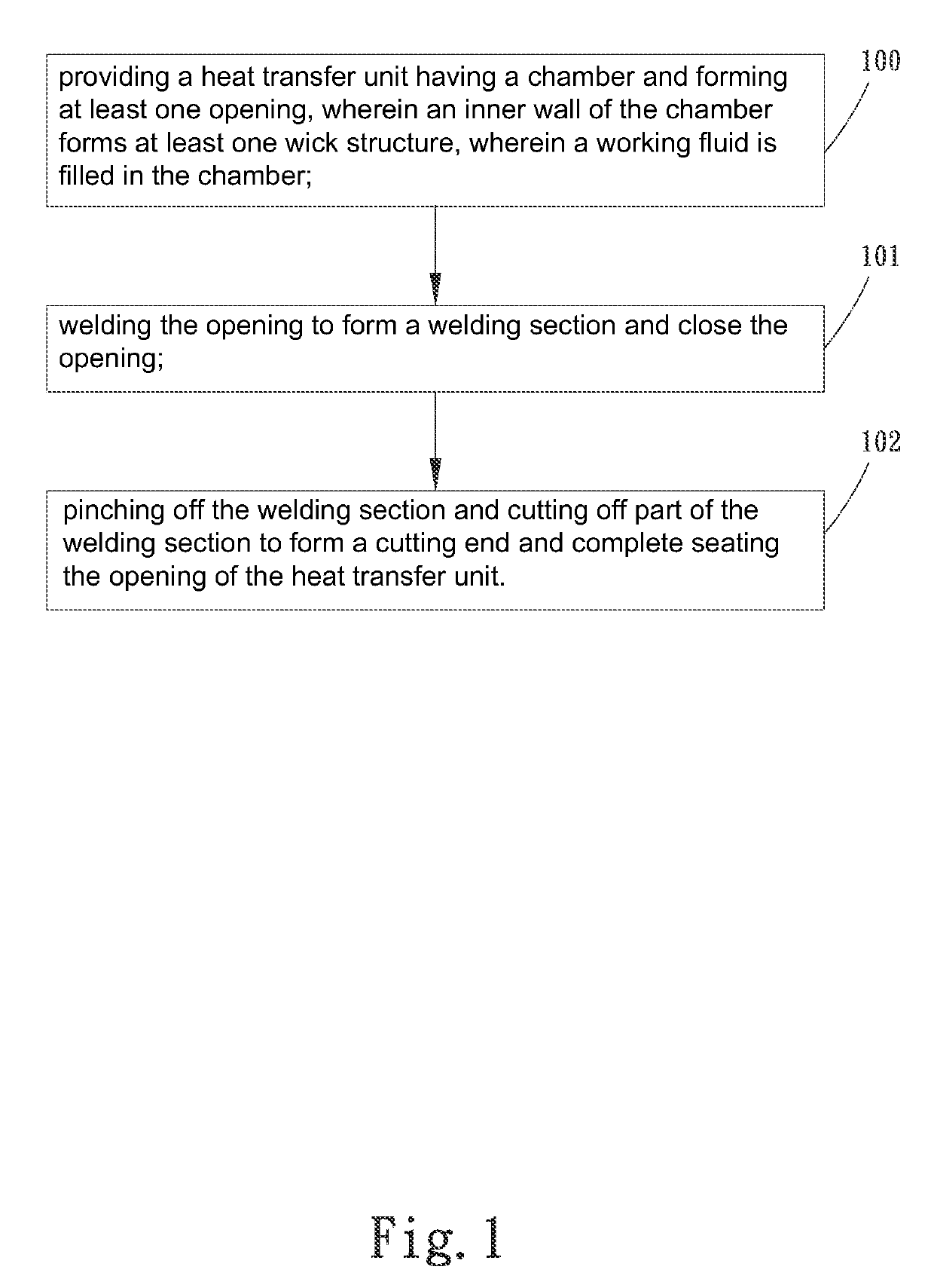
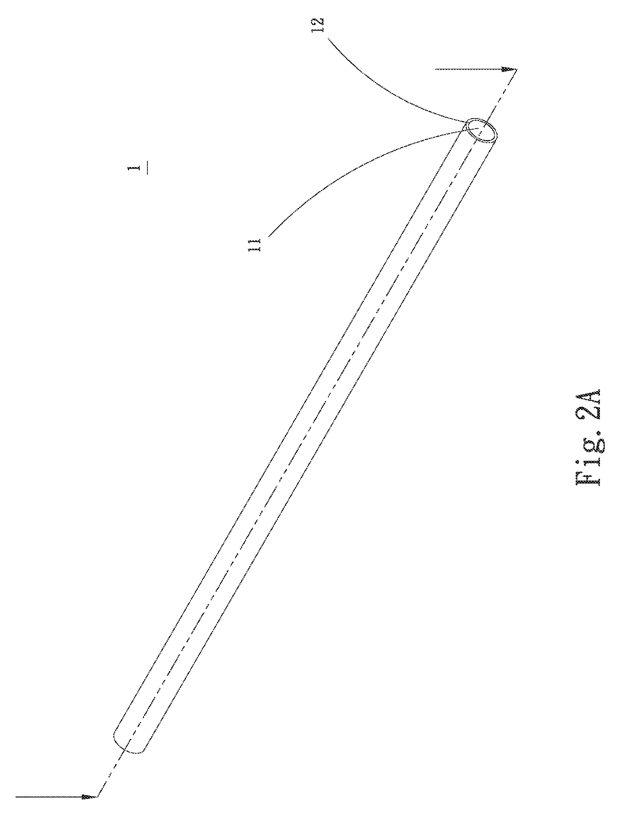
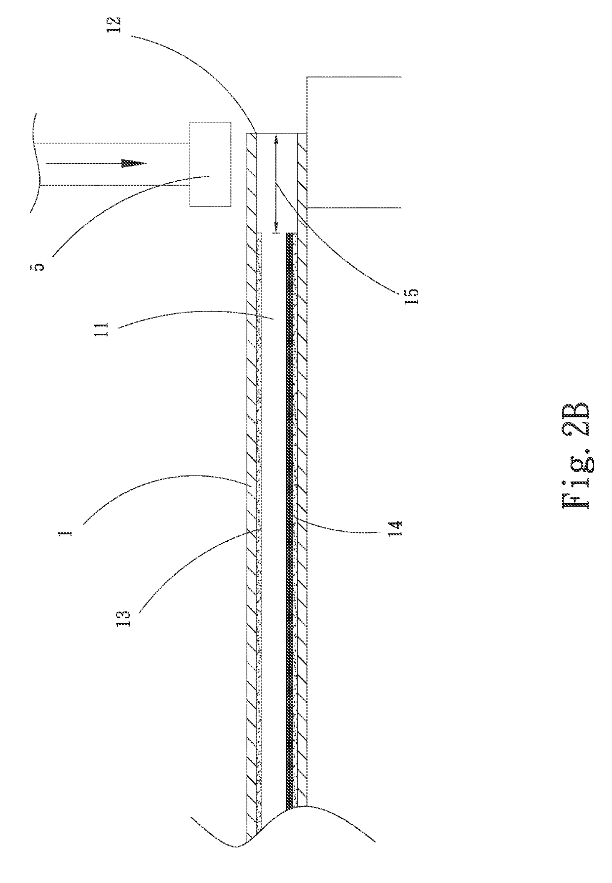
[0025]The present invention is to provides a method of removing the dead zone of a flat heat pipe. Please refer to FIG. 1, which is a flow chart of the method for sealing a heat transfer unit according to the first embodiment of the present invention. Please also refer to FIGS. 2A, 2B, 2C, 2D, and 3. In the current embodiment, a cylindrical heat pipe is used as an example of the heat transfer unit 1 for explanation. The method for sealing a heat transfer unit includes the following steps.

[0026]Step (100): providing a heat transfer unit having a chamber and forming at least one opening, wherein an inner wall of the chamber forms at least one wick structure, wherein a working fluid is filled in the chamber.

[0027]The heat transfer unit 1 which is a cylindrical heat pipe is provided. The heat transfer unit 1 has a chamber 11 therein; each of two ends of the heat transfer unit 1 has an opening 12 communicating with the chamber 11. An inner wall of the chamber 11 forms at least one wick s...


PUM

PropertyMeasurementUnit
lengthaaaaaaaaaa
heat conduction efficiencyaaaaaaaaaa
heataaaaaaaaaa

Abstract

The present invention relates to a method for sealing a heat transfer unit, which includes the steps of providing a heat transfer unit having at least one opening, welding the opening to form a welding section and close the opening, and pinching off the welding section and cutting part of the welding section to form a cutting end and complete sealing the opening of the heat transfer unit. By means of the method of the present invention, an extremely short dead zone can be obtained and high heat conduction efficiency is enhanced, further having the effects of reducing the arrangement space and shrinking steps of the heat pipe.

Description

BACKGROUND OF THE INVENTIONField of the Invention[0001]The present invention relates to a method for sealing a heat transfer unit and in particular to a method for sealing a heat transfer unit, which significantly reduces the length of the dead zone and improves heat conduction efficiency.Description of Prior Art[0002]With the rapid development of electronic information industry, the processing capability of the electronic device such as a CPU increasingly grows with the increasing generated heat. The heat-dissipation module combining a heat-dissipation fin and a fan has not been able to meet the requirement of heat dissipation, especially for a notebook computer. The heat pipe is a currently and commonly used device for heat transfer. The heat pipe can be considered a passive heat transfer device with high heat conductivity. Using the mechanism of two-phase heat transfer, the heat transfer capability of the heat pipe is hundreds times as large as copper having the same size. The he...

Claims


Application Information

Patent Timeline
Patent Type & Authority Patents(United States)
IPC IPC(8): B23P15/26H01L21/48F28D15/04F28D15/02H01L23/427
CPCB23P15/26F28D15/0283F28D15/04H01L21/4882H01L23/427B23P2700/09F28F2255/00F28F2275/06
Inventor YANG, HSIU-WEI
Owner ASIA VITAL COMPONENTS SHENZHEN CO LTD
Why Eureka
Try Eureka