
Method and device for detecting a tiredness and/or sleeping state of a driver of a vehicle

a technology for drivers and vehicles, applied in diagnostics, diagnostic recording/measuring, instruments, etc., can solve problems such as dangerous situations or accidents, and achieve the effects of robust recognition, reduced future acceptance, and easy realization

Active Publication Date: 2019-06-04
ROBERT BOSCH GMBH
View PDF10 Cites 0 Cited by
  • Summary
  • Abstract
  • Description
  • Claims
  • Application Information

AI Technical Summary

Benefits of technology

[0012]The approach presented here is based on the recognition that a very robust recognition of the state of tiredness and / or sleep of the driver is possible when a plausibilized first and / or second eye opening signal is used for such a recognition. In this way, the ascertaining of a false value for a state of tiredness and / or sleep of the driver, due to measurement errors in the acquisition of a parameter of the eye or eyelid, can be excluded, or at least prevented to a great extent. The approach presented here thus offers the advantage of a significantly more robust and more reliable recognition of the state of tiredness and / or sleep of the driver, whereby false or erroneous warnings to the driver can be suppressed. This leads to a significant increase in the degree of acceptance by the driver of the tiredness recognition or sleep recognition, so that a corresponding warning has a higher probability of being taken seriously by the driver.
[0026]The approach presented here thus provides a device that is fashioned to carry out, control, or realize the steps of a variant of a method presented here in corresponding devices. Through this variant embodiment of the present invention in the form of a device as well, the underlying object of the present invention can be achieved quickly and efficiently.

Problems solved by technology

Sleepiness and microsleeps at the steering wheel frequently cause dangerous situations or accidents.

Method used


Image

  • Method and device for detecting a tiredness and/or sleeping state of a driver of a vehicle
  • Method and device for detecting a tiredness and/or sleeping state of a driver of a vehicle

Examples


Embodiment Construction

[0034]In the following description of advantageous exemplary embodiments of the present invention, the elements shown in the various Figures and having similar function are provided with identical or similar reference characters, and repeated description of these elements is omitted.

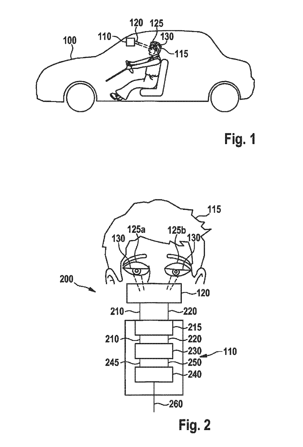
[0035]FIG. 1 shows a schematic diagram of a vehicle 100 that has an exemplary embodiment of a device 110 for recognizing a state of tiredness and / or state of sleep of a driver 115 of vehicle 100. Device 110 is here connected to a camera 120 that acquires eyes 125 of driver 115, in particular a position of an eyelid 130 of the left and / or right eye 125, and from this ascertains a degree of eye opening of the respective eye 125.

[0036]FIG. 2 shows a schematic diagram of a system 200 for recognizing a state of tiredness and / or state of sleep of driver 115 of the vehicle, having a device 110 for recognizing the state of tiredness and / or sleep of driver 115 of a vehicle. Here, camera 120 sends a first eye open...


PUM


Abstract

A method for recognizing a state of tiredness and / or sleep of a vehicle driver. The method includes reading in a first and second eye opening signal, the first signal representing a degree of eye opening and / or a signal derived therefrom of the left eye of the driver of the vehicle and the second signal representing a degree of eye opening and / or a signal derived therefrom of the right eye of the driver of the vehicle. The method also includes recognizing a validity of the first and / or second signal to recognize the first signal as valid if the first signal corresponds to a first criterion and / or to recognize the second signal as valid if the second eye signal corresponds to a second criterion, and determining the state of tiredness and / or sleep of the driver of the vehicle using the first signal recognized as valid and / or the second signal recognized as valid.

Description

FIELD OF THE INVENTION[0001]The present invention relates to a method for recognizing a state of tiredness and / or state of sleep of a driver of a vehicle, to a corresponding device, and to a corresponding computer program.BACKGROUND INFORMATION[0002]Sleepiness and microsleeps at the steering wheel frequently cause dangerous situations or accidents. Sleepiness recognizers for example output a warning when the driver exceeds a certain sleepiness boundary value (=coffee cup symbol).[0003]This warning can however be ignored by the driver. Microsleeps are not recognized as a separate danger by many sleepiness assistants, and thus a timely warning does not take place.[0004]Sleepiness recognition systems indirectly estimate the tiredness of the driver from the driving behavior. Microsleep is not taken into consideration as a separate source of danger.[0005]Systems are also known that, using data from a video camera, can recognize the momentary degree of opening of the eyes (e.g. SmartEye, ...

Claims


Application Information

Patent Timeline
Patent Type & Authority Patents(United States)
IPC IPC(8): G08B23/00G08B21/06B60Q9/00G06K9/00
CPCG08B21/06B60Q9/00G06K9/00845G06K9/00597B60Y2302/03A61B5/1103A61B5/1128A61B5/18A61B5/746G06V20/597G06V40/18
Inventor WULF, FELIX
Owner ROBERT BOSCH GMBH
Learn More