
Glasses-free autostereoscopic 3D display device

a display device and glass-free technology, applied in optics, instruments, electrical appliances, etc., can solve the problems of image quality deterioration, application difficulty in reality, deterioration of image flipping phenomenon, etc., to reduce the number of image sources, reduce the cost, and reduce the effect of 3d crosstalk

Active Publication Date: 2019-06-04
LG DISPLAY CO LTD
View PDF15 Cites 1 Cited by
  • Summary
  • Abstract
  • Description
  • Claims
  • Application Information

AI Technical Summary

Benefits of technology

The present patent aims to provide an autostereoscopic 3D display device that can minimize visual interference, image flipping, and luminance difference in stereoscopic images, thus enhancing the depth of the images. This device can allow for the input and output of stereo type image data, reducing the number of image sources and cost associated with 3D crosstalk. Additionally, the device can apply view data rendering to remove image quality deterioration in a 2D zone, extending the 3D viewing zone.

Problems solved by technology

Accordingly, an image difference between first view data and last view data increases as the number of views increases, thereby deteriorating the phenomenon of image flipping.
In the case of directly receiving a multi-view image, application is difficult in reality since a lot of cost is incurred for the image production, and the number and structure of views required are different for different stereoscopic 3D display devices and configurations.
In this case, it may cause image quality deterioration due to the absence of the amount of information and depth reduction due to inner view generation.
Furthermore, a multi-view converter is essentially required, and the size of chip and system increases and the time and cost increases as the number of operations applied to compensate for image quality deterioration increases.

Method used


Image

  • Glasses-free autostereoscopic 3D display device
  • Glasses-free autostereoscopic 3D display device
  • Glasses-free autostereoscopic 3D display device

Examples


first embodiment

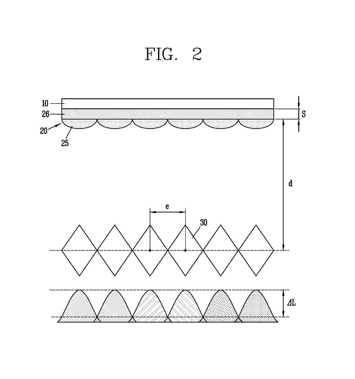
[0147]In the case of the present disclosure, it is seen that luminance difference (ΔL′) is greatly reduced compared to the related art when the viewing diamonds 130 are configured to overlap with each other compared to a lenticular lens type stereoscopic 3D display device in the related art.

[0148]Here, a two overlapping views embodiment (where a viewing diamond 130 overlaps with two adjacent viewing diamonds) is taken as an example in FIG. 5, but the present disclosure is not limited to this, and three or more overlapping viewing diamonds may be used. Here, using two overlapping views has a structure in which another viewing diamond 130 is inserted between two adjoining viewing diamonds 130.

[0149]Here, the size and width of a light profile in each view are affected by the image panel 110, lenticular lens sheet 120, light source, optical sheet, and the like, and the size of a region overlapping with the light profile of a view corresponding to the adjoining viewing diamond 130 corres...

second embodiment

[0225]FIG. 17 is a view illustrating a view structure and view data of an autostereoscopic 3D display device according to the present disclosure, as an example.

[0226]Here, FIG. 17 illustrates a view structure and view data of an autostereoscopic 3D display device to which an NVD technology is applied, as an example. Furthermore, FIG. 17 illustrates an eight-view, two-overlapping views structure, as an example. However, the present disclosure is not limited to such a number of views and number of overlapping views.

[0227]Referring to FIG. 17, the number of views is eight at this time, and an NVD technology is applied, and thus the view distance (d2) corresponds to quarter of the interocular distance (e), namely, 16.25 mm.

[0228]In other words, when the size of the viewing diamond 230 is set to half of the interocular distance (e) (hereinafter, referred to as “NVD ½-based” for the sake of convenience of explanation) and a two overlapping views structure is applied thereto, the view dist...

third embodiment

[0240]Accordingly, the present disclosure forms a view map and 3D filter with a modified format as follows.

[0241]FIG. 19 is a view illustrating another view structure and view data of an autostereoscopic 3D display device according to the third embodiment of the present disclosure, as an example.

[0242]Here, FIG. 19 illustrates a view structure and view data of an autostereoscopic 3D display device to which an NVD technology is applied, as an example. Furthermore, contrary to the foregoing embodiment of FIG. 17, FIG. 19 illustrates a nine-view, 2-overlapping views structure, as an example. In other words, one view is further added and configured with a nine-view structure when compared to the foregoing embodiment of FIG. 17. However, the present disclosure is not limited to such a number of views and overlapping number of views.

[0243]Referring to FIG. 19, the number of views is nine at this time, and an NVD technology is applied, and thus the view distance (d2) corresponds to quarter...


PUM


Abstract

An autostereoscopic 3D display device may be configured to set the width of a viewing zone to a proper fraction of the interocular distance while at the same time overlapping the viewing zones with each other. Through this, an autostereoscopic 3D display device allowing the input and output of stereo image data may be implemented to reduce the number of image sources as well as reduce 3D crosstalk. In addition, the autostereoscopic 3D display device may apply view data rendering to extend a 3D viewing zone.

Description

CROSS-REFERENCE TO RELATED APPLICATIONS[0001]This application claims the benefit of Korean Patent Application No. 10-2014-0191080, filed on Dec. 26, 2014, which is hereby incorporated by reference for all purposes as if fully set forth herein.BACKGROUND[0002]1. Field of the Invention[0003]The present invention relates to a stereoscopic 3D display device, and more particularly, to a glasses-free autostereoscopic 3D display device.[0004]2. Description of the Related Art[0005]Three-dimensional (3D) display may be briefly defined as “all types of systems for artificially generating a 3D screen.”[0006]A system may include software technologies that produce three-dimensional images and hardware for actually displaying 3D content made by the software technologies. The systems typically include a software component because 3D content produced with a particular software scheme are separately required for each 3D stereoscopic display hardware implementation.[0007]Furthermore, virtual 3D displ...

Claims


Application Information

Patent Timeline
Patent Type & Authority Patents(United States)
IPC IPC(8): H04N13/302H04N13/305H04N13/31H04N13/317H04N13/324H04N13/383G02B27/22H04N13/349G02B30/29
CPCH04N13/302G02B27/2214H04N13/305H04N13/383H04N13/317H04N13/324H04N13/349H04N13/31G02B30/29H04N13/30G02B30/23G02B30/27
Inventor AN, CHUNGHWAN
Owner LG DISPLAY CO LTD
Learn More