Hollow forging process for main shaft of large wind turbine generator

a wind turbine generator and hollow forging technology, which is applied in forging/pressing/hammering equipment, furnaces, heating/cooling devices, etc., can solve the problems of 3 mw having no free forging oil presses with a larger capacity, the main shaft of 3.0 mw offshore wind turbine generator cannot be processed by solid forging methods, etc., to improve the fatigue resistance of the main shaft, improve the efficiency, and the effect of small siz

Active Publication Date: 2019-06-11
JIANGYIN ZENKUNG FORGING CO LTD
View PDF0 Cites 2 Cited by
  • Summary
  • Abstract
  • Description
  • Claims
  • Application Information

AI Technical Summary

Benefits of technology

[0007]The technical scheme adopted to solve the technical problem in the Invention is to provide a hollow forging process for main shaft of large wind turbine generator which comprises the following steps as: the first step of cutting off the dead head and the bottom of an ingot; the second step of upsetting and punching a hole; the third step of drawing-out; and the fourth step of local upsetting, drawing-out and shaping-up. The main specifications of the forged main shaft are as follows: the outer diameter of flange is Ø2260; the steps of the forged piece are respectively Ø1150, Ø1060, Ø1000, Ø860 and Ø740; the through-hole is Ø350 and the length is 3100; using the free forging oil press of 3150 T, the main shaft with such specifications can be forged by the hollow forging method rather the solid forging method. Moreover, the material can be saved to some extent. Taking the main shaft with the specifications as an example, it may consume 33.5 T of steel ingot to forge one piece by the solid forging method, while only 30 T by the hollow forging method. Accordingly, the weight of the forged piece is lighter than that forged by the solid forging method. Meanwhile, it may reduce the working hour to roughly process the through-hole (for a solid forged piece, it shall be punched firstly and then bored to a certain size of inner hole step by step; while the inner hole size of a hollow forged piece is already 350, it only needs to process a thickness of 40 for each side to reach the due size of 430, which reduces the working hour) and thus improves the efficiency. In addition, the hollow forged main shaft is punched before being drawn out, so the fiber texture is continuous, while the fiber texture of that by the solid forging method is cut off during hole processing (in which punching is the last step) (the continuous fiber texture can improve the fatigue resistance of the main shaft and upon many years of researches on the wind turbine generator in many European and American countries, it shows that the main factor for damaging the main shaft is not the short-term load but the long-term fatigue stress). The forged piece with quenched-tempered heat treatment is light-weighted and the heating consumption is reduced. Customers are satisfied with such main shaft with low cost, high profit and low sales price than that processed by the solid forging method.
[0008]As a further improvement of the hollow forging process for main shaft of large wind turbine generator herein, in the fourth step, the forged piece is shaped up by local upsetting and drawing-out through a turnplate; the turnplate comprises a circular turnplate base and a turnplate body connected to the turnplate base; a circular hole that matches the shape of the lower end of the main shaft to be processed is arranged on the turnplate body; a hole with a certain taper is arranged in the middle of the turnplate base, which may ensure that both excircle and inner hole of the main shaft will not result in eccentricity against the same taper of core rod. Such special structure of the turnplate can keep a same center for the excircle and the inner hole.
[0009]As a further improvement of the hollow forging process for main shaft of large wind turbine generator herein, the core rod overall takes the shape of a conic cylinder; the head of the core rod is cylindrical; the fillet radius of the end of the core rod is 30-50 mm and the taper of the core rod is 1:100. The cylindrical head of the core rod is designed to have a stop function, preventing the core rod falling down further.
[0010]As a further improvement of the hollow forging process for main shaft of large wind turbine generator herein, in the third step, the process of drawing-out is conducted by a drawing-out core rod. The drawing-out core rod is overall cross-shaped; the transverse core rod body that forms the cross-shape abuts against a flange plate face of the main shaft in the process of drawing-out so as to prevent material escaping from the through-hole in the center of the main shaft. The core rod may prevent the diameter of the inner hole becoming smaller than the target size in the process of drawing-out. The core rod is remanufactured with a scrapped forged piece in order to save costs.
[0017]The forging equipment used in the Invention can be that with a smaller size, so that the main shaft of large wind turbine generator, especially that of above 3.0 MW can be produced with the existing equipment. Through the forging process, the material can be saved to some extent and the weight of the forged piece is lighter than that forged by the solid forging method. Meanwhile, it may reduce the working hour to roughly process the through-hole and thus improves the efficiency. In addition, the fiber texture of the hollow forged main shaft is continuous, improving the fatigue resistance of the main shaft. The forged piece with quenched-tempered heat treatment is light-weighted and the heating consumption is reduced. Customers are satisfied with such main shaft with low cost, high profit and low sales price than that processed by the solid forging method. The forging process also takes full consideration into the high requirements for multi-hole forging and ensures both excircle and inner hole will not result in eccentricity.

Problems solved by technology

The main shaft is mainly used in the offshore wind turbine generator, and climatic condition, especially typhoon, is always taken as a main problem for consideration in designing the offshore wind turbine generator.
Therefore, it is the most important challenge to improve the resistance to typhoon of the main shaft.
At present, the main shaft of 3.0 MW for the offshore wind turbine generator can't be processed by solid forging method, with a free forging oil press of 3150 T. The worse thing is that many enterprises that produce the main shaft less than 2.3 MW have no free forging oil presses with a larger capacity.
Therefore, it is a problem to process the main shaft of 3.0 MW for the large wind turbine generator with the existing equipment.

Method used


Image

  • Hollow forging process for main shaft of large wind turbine generator
  • Hollow forging process for main shaft of large wind turbine generator
  • Hollow forging process for main shaft of large wind turbine generator

Examples


Embodiment Construction

[0023]The embodiments of the Invention will be further described in combination with the drawings as follows to make the technical features, purpose, and effectiveness of the Invention clearer.

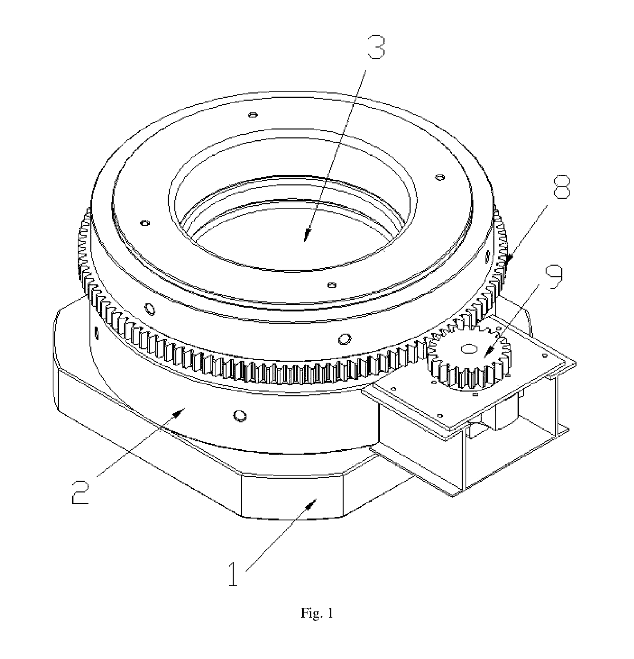
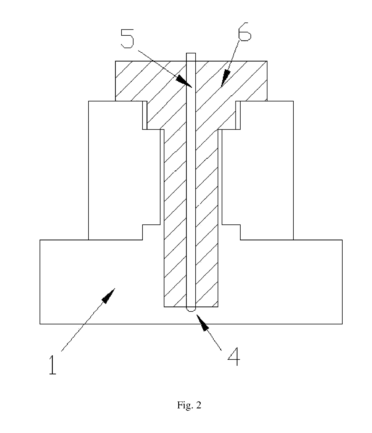
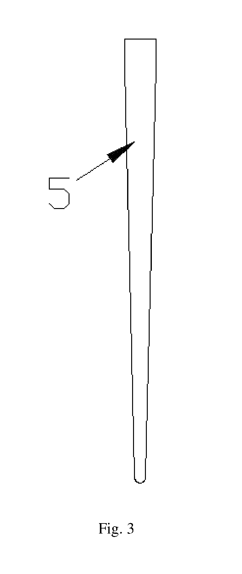
[0024]A hollow forging process for main shaft of large wind turbine generator comprises the following steps as: the first step of cutting off the dead head and the bottom of an ingot; the second step of upsetting and punching a hole; the third step of drawing-out; and the fourth step of local upsetting, drawing-out and shaping-up. In the fourth step, the forged piece is shaped up by local upsetting and drawing-out through a turnplate; as shown in FIGS. 1-4, the turnplate comprises a circular turnplate base 1 and a turnplate body 2 connected to the turnplate base 1; a circular hole 3 that matches the shape of the lower end of the main shaft 6 to be processed is arranged on the turnplate body 2; a hole 4 with a certain taper is arranged in the middle of the turnplate base 1, which may ensure bot...


PUM

PropertyMeasurementUnit
fillet radiusaaaaaaaaaa
temperatureaaaaaaaaaa

Abstract

A hollow forging process for main shaft of large wind turbine generator, wherein, comprising the following steps as: the first step of cutting off the dead head and the bottom of an ingot; the second step of upsetting and punching a hole; the third step of drawing-out; and the fourth step of local upsetting, drawing-out and shaping-up. In the fourth step, the forged piece is shaped up by local upsetting and drawing-out through a turnplate. The hollow forging process for main shaft created by the invention can save the costs for enterprise to purchase large equipment and makes it possible to forge the main shaft of large wind turbine generator with a free forging oil press with a smaller size.

Description

CROSS-REFERENCE TO RELATED APPLICATIONS[0001]The present application claims the benefit of Chinese Patent Application No. 201610726344.X filed on Aug. 26, 2016, the contents of which are hereby incorporated by reference.TECHNICAL FIELD[0002]The Invention relates to hollow forging process for main shaft of wind turbine generator, and particularly to a hollow forging process for main shaft of large wind turbine generator.BACKGROUND ART[0003]The main shaft of wind turbine generator is one of the key parts of a wind turbine generator. Offshore wind power generation is a technology integrated with multiple disciplines as computer technology, aerodynamics, structural mechanics and material science. With the continuous improvement of wind power generation technology and the constant reduction of the costs for manufacturing generator set, the market competitiveness of offshore wind power generation will be gradually promoted with a vast potential for future development.[0004]The main shaft ...

Claims


Application Information

Patent Timeline
Patent Type & Authority Patents(United States)
IPC IPC(8): C21D9/08C22C38/04C21D8/10B21J5/02F03D80/80B21J5/08B21J5/10B21K1/06B21K1/10F03D15/00B22D7/00B22D29/00C22C38/22C22C38/44
CPCC21D9/08B21J5/022B21J5/08B21J5/10B21K1/063B21K1/10B22D7/00B22D29/00C21D8/105C22C38/04C22C38/22C22C38/44F03D15/00F03D80/88B21J5/02Y02P70/523F05B2230/10F05B2230/25F05B2240/61Y02E10/72B21J1/06B21J5/06B21K29/00Y02P70/50
Inventor QI, ZHENHUAMA, SHENGYILIU, SHENGXIANGYAN, ZHENWEI
Owner JIANGYIN ZENKUNG FORGING CO LTD
Why Eureka
Try Eureka