Eureka AIR delivers breakthrough ideas for toughest innovation challenges, trusted by R&D personnel around the world.

Universal joint

a universal joint and joint technology, applied in the field of universal joints, can solve the problems of affecting the operation life of the drill string including the universal joint, affecting the operation life of the drill string components, and affecting the operation of the drill string, so as to shorten the drill string, and reduce the risk of slipping

Active Publication Date: 2019-06-11
ULTERRA DRILLING TECH LP
View PDF29 Cites 2 Cited by
  • Summary
  • Abstract
  • Description
  • Claims
  • Application Information

AI Technical Summary

Benefits of technology

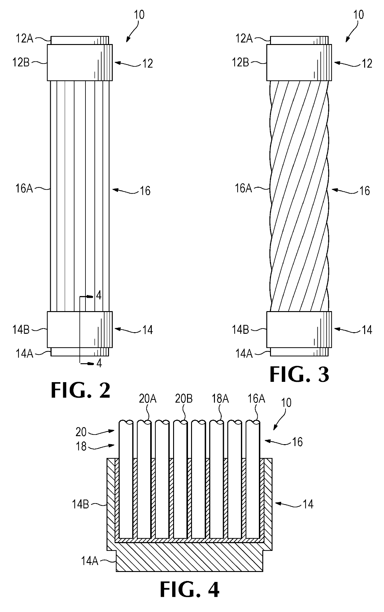
[0006]The present invention relates to a universal joint to be used as part of a downhole drill string. A joint in accordance with the invention can be inexpensive to manufacture, a single component without conventional bearing surfaces, and / or durable with limited erosion and wear susceptibility. Two terminating members are attached to each end of a cable. The cable with terminating members is flexible, and when used to connect two rotating shafts, accommodates misalignment of the shafts. In one embodiment, the joint can provide transmission of thrust as well as torque. The inventive joint can provide a compact assembly that allows the components of the drill string to be positioned closer together, which can in turn shorten the drill string.
[0007]The cable is preferably composed of a plurality of strands with each strand being thin in relation to its length. The strands are of a flexible material and the cable generally has greater stiffness than the individual strands. This configuration limits abrasion and erosion that normally occurs in conventional downhole universal joints on account of the high forces transmitted through sliding or rotating contact surfaces. A stranded cable is less subject to fretting and spalling at mating surfaces.

Problems solved by technology

The components of the drill string including the universal joint are subjected to extreme torque forces, elevated operating temperatures and abrasive drilling fluids, all of which can have an adverse effect on the operational life of drill string components.
Constant relative movement of the components of a universal joint during operations, together with abrasive drilling mud, causes abrasion and erosion of mating components.
However, the constant relative movement of the components and aggressive downhole environment leads to difficulties in conventional sealing arrangements.
Replacement of the joint or its components requires removal of the drill string from the borehole and downtime for the operation, which increases operational expenses substantially.

Method used


Image

  • Universal joint
  • Universal joint
  • Universal joint

Examples


Embodiment Construction

[0022]A drill string in its basic form consists of sections of threaded pipe and tools assembled end to end with a drill bit at a distal end for advancing a borehole. The drill string can be miles long and rotated at a proximal end of the pipe by a drilling rig (or otherwise) to turn the drill bit and advance the borehole. There are many different kinds of supplemental components that can be assembled to the drill string to perform a range of functions such as reaming out obstructions from the borehole, widening the borehole or vibrating to limit friction between the string and the borehole.

[0023]Positive displacement or mud motors can be installed at the distal end of the drill string to drive the drill bit instead of, or in addition to, driving the drill string from the above ground drill rig. Fluid is pumped down the drill string during operation under pressure to flush material out of the borehole. A mud motor uses the pressure of the fluid to drive a rotor in a stator housing. ...


PUM


Abstract

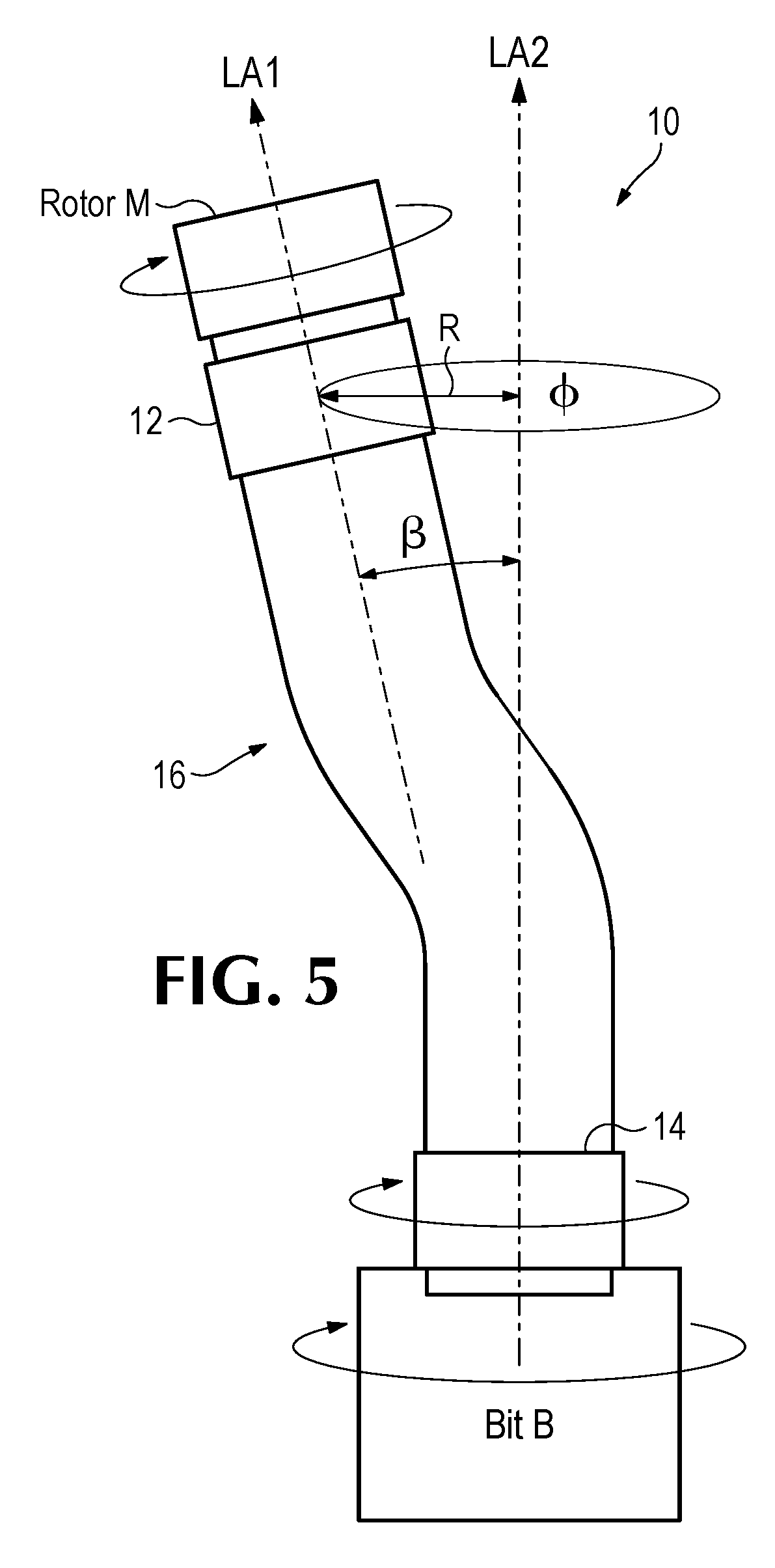
A universal joint assembled to a drill string transfers torque and axial force between two components where the shafts of the components are not completely aligned. The universal joint includes end members connected to opposite ends of a cable for connecting to components of the drill string. As the joint rotates the cable flexes to accommodate misalignment between the connected drill string components.

Description

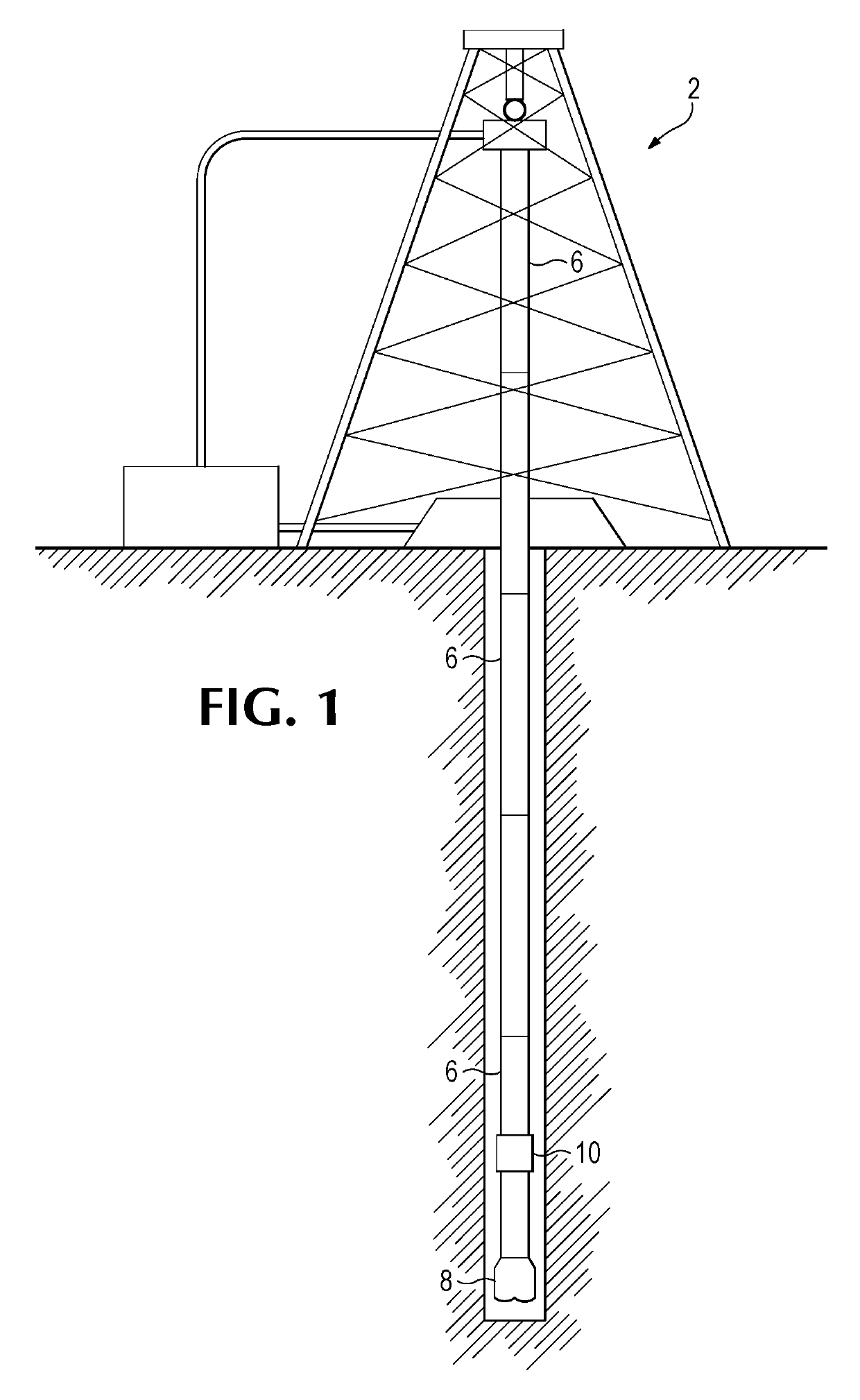
FIELD OF THE INVENTION[0001]This invention relates to universal joints for downhole drilling operations.GENERAL BACKGROUND[0002]Universal joints are used in mechanical applications to transmit torque between components where there can be misalignment of rotating parts. In a drilling operation, a drill bit is mounted to the end of a drill string. The drill string is rotated from the top of the string or by a motor at the bottom of the string, or both, to rotate the drill bit and advance the borehole. Universal joints are included in the drill string to accommodate rotational eccentricity. The eccentric rotation is converted into axial rotation in order for the drill bit to advance the borehole efficiently. Eccentricity can be initiated by a motor in the drive assembly that rotates the drill bit or by steering of the bit to change direction of the borehole.[0003]FIG. 1 is a schematic representation of a drilling operation 2. In conventional drilling operations a drill bit 8 is mounted...

Claims


Application Information

Patent Timeline
Patent Type & Authority Patents(United States)
IPC IPC(8): E21B17/20F16D3/56
CPCE21B17/20F16D3/56
Inventor MCMILLAN, JUSTIN S.CASAD, CHRISTOPHER M.ST. PIERRE, BEAU J.DEEN, CARL ARON
Owner ULTERRA DRILLING TECH LP
Why Eureka
Eureka Blog
Learn More