Water cooled vaporizing system

a water vaporizing system and water cooled technology, applied in the direction of evaporator regulation/control, tobacco, separation process, etc., to achieve the effects of low manufacturing cost, convenient and efficient manufacturing and marketing, and durable and reliable construction

Inactive Publication Date: 2019-06-18
KANE RANDY M
View PDF24 Cites 16 Cited by
  • Summary
  • Abstract
  • Description
  • Claims
  • Application Information

AI Technical Summary

Benefits of technology

[0013]It is another object of the present invention to provide a new and improved vaporizing system which may be easily and efficiently manufactured and marketed.
[0014]It is a further object of the present invention to provide a new and improved vaporizing system which is of durable and reliable constructions.
[0015]An even further object of the present invention is to provide a new and improved vaporizing system which is susceptible of a low cost of manufacture with regard to both materials and labor, and which accordingly is then susceptible of low prices of sale to the consuming public, thereby making such vaporizing system economically available to the buying public.
[0016]Lastly, it is an object of the present invention to provide a vaporizing system for selective heating of vaporizing material to a heated vapor above, and for spinning, percolating and agitating a quantity of water below, and for passing the vaporized material as heated vapors through the water to cool, cleanse and enhance the flavor and create inhalable cooled vapor, the heating and the agitating and the passing all being done in a safe, medically-acceptable+, convenient, and economical manner.

Problems solved by technology

While these known devices fulfill their respective, particular objectives and requirements, including tobacco and medical marijuana, they do not describe a vaporizing system that allows for the selective vaporizing of herbs, oils, liquids and concentrates to a heated vapor, and for agitating a quantity of water below, and for passing the vaporized material as heated vapor through the water to cleanse and cool an enhance the flavor and create an inhalable cooled vapor.

Method used


Image

  • Water cooled vaporizing system
  • Water cooled vaporizing system
  • Water cooled vaporizing system

Examples


Embodiment Construction

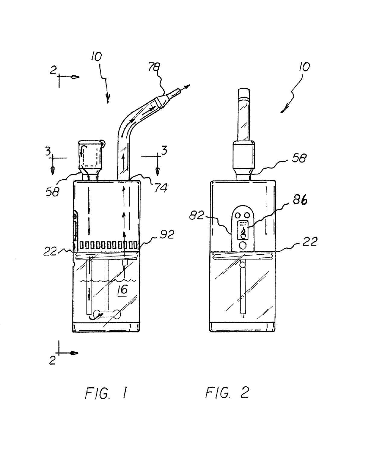
[0029]With reference now to the drawings, and in particular to FIG. 1 thereof, the preferred embodiment of the new and improved water cooled vaporizing system embodying the principles and concepts of the present invention and generally designated by the reference numeral 10 will be described.

[0030]The present invention, the vaporizing system 10 is comprised of a plurality of components. Such components in their broadest context include a housing assembly, an agitation assembly, and an inlet assembly, a heating assembly, and an outlet assembly. Such components are individually configured and correlated with respect to each other so as to attain the desired objective.

[0031]From a specific perspective, the invention of the present application is a vaporizing system for selective heating of herbal material 12 to a heated vapor 14, for agitating and percolating a quantity of water 16, and for passing vaporized material through the water to create an inhalable cooled vapor 18. The heating...


PUM


Abstract

A housing assembly is formed of upper and lower cases with top and bottom plates and an intermediate plate separating the upper and lower cases. An agitation assembly includes water in the lower case. A plurality of paddles submerged in the water are rotatable to agitate the water. An inlet assembly includes an inlet pipe having a top end above the top plate and a bottom end submerged in the water. A heating assembly includes a chamber interiorly and a cylinder exteriorly forming an annular passageway terminating at the top end of the inlet pipe. A heating coil system within the vaporizing chamber is adapted to vaporize the selected material whereby vapors released will tumble down the annular passageway then down the inlet pipe into the water. An outlet assembly includes an outlet pipe having a top end and a bottom end terminating below above the water.

Description

BACKGROUND OF THE INVENTIONField of the Invention[0001]The present invention relates to a 3 in 1 water cooled vaporizing system which, allows for a single unit to vaporize herbs, oils, liquids, and concentrates, including tobacco or medicinal marijuana, the vaporizing being done in an improved, safer, more versatile hookah, water pipe style. The system is a smokeless system that heats up the herbal material Instead of combustion, the vaporizing process utilizes a conduction method for the purpose of creating inhalable vapors which cause the essential oils, which contain the active ingredients of the herbal material, to boil until it creates a cooled vapor that can be safely inhaled.[0002]The purpose of this invention is to allow for the user to select a material to be vaporized and place it in 1 of 3 specifically newly created conduction vaporizing chambers that allows for the vaporized material to be drawn downward into the water reservoir where spinning paddles agitate and percola...

Claims


Application Information

Patent Timeline
Patent Type & Authority Patents(United States)
IPC IPC(8): A24F47/00A61M15/00A61M11/04A24F1/30H02J7/00A24F40/46A24F40/485A24F40/50A24F40/60
CPCA24F47/008A24F1/30A61M15/0021H02J7/0052A61M11/042H02J2007/0062B01D1/0011B01D1/0082A24F40/485A24F40/46A24F40/60A24F40/50A61M15/06A61M2205/8256A61M2205/583A61M2205/8206H02J7/00
Inventor KANE, RANDY M.
Owner KANE RANDY M
Why Eureka
Try Eureka