Eyeglasses equipment including a joint and method for manufacturing such an eyeglasses equipment

a technology of eyeglasses and equipment, which is applied in the field of eyeglasses, can solve the problems of not being able to select all the opticians' frames, putting constraints on lenses, and neither method is really flexible, and achieves the effects of easy installation, easy machine or remanufacture, and good lens bearing

Active Publication Date: 2019-07-02
ESSILOR INT CIE GEN DOPTIQUE
View PDF15 Cites 0 Cited by
  • Summary
  • Abstract
  • Description
  • Claims
  • Application Information

AI Technical Summary

Benefits of technology

[0022]More precisely, the invention consists in an eyeglasses equipment including a frame, at least one ophthalmic lens, and an interface that is situated between said frame and said lens and that is colored in such a manner that it reduces halos.
[0049]Another advantage of the joint is that, if there is a misfit between the joint and the frame or between the joint and the lens, the joint may be easily machined or remanufactured, without any consequence because this joint is less expensive than the lenses and the frame.

Problems solved by technology

Neither of those two methods is really flexible.
Because all combinations of lens are not accessible with the right curvature and diameter of the surrounds of the selected frame, some people can not select all the optician's frames, because of their vision deficiencies.
Another problem of the known solutions is that the assembly of the lenses into the frame put constraints on the lenses.
For example, all lens edge thicknesses are not compatible with half-rimmed frames.
Moreover, once the eyeglasses are assembled, it is not easy for wearers to modify the aesthetical aspect of their piece of eyewear.
In addition to these various drawbacks, such an assembly has a major disadvantage that we would like to solve.
This disadvantage mainly affects lenses for myopic people, whose thicknesses at the edges are great.
Thus these halos are not only unsightly (for people who look at the wearer), but also unpleasant for the wearer (especially when he sees himself on photos taken with a raking light).

Method used


Image

  • Eyeglasses equipment including a joint and method for manufacturing such an eyeglasses equipment
  • Eyeglasses equipment including a joint and method for manufacturing such an eyeglasses equipment
  • Eyeglasses equipment including a joint and method for manufacturing such an eyeglasses equipment

Examples


third embodiment

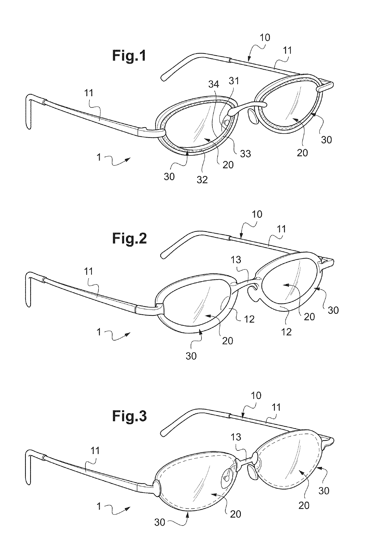
[0113]In a third embodiment, the joint 30 and the associated lens 20 may form a single piece (see FIG. 3).

[0114]In these embodiments, the joint 30 is advantageously made from a material that is different from the material of the lens 20 and that is also different from the material of the frame 10. In practice, the joint 30 is manufactured by a process that is different from the process used to manufacture said lens 20 and that is also different from the process used to manufacture said frame 10.

[0115]In the embodiment of FIG. 1, where the joint 30 acts as a mechanical interface between the lens 20 and the frame 10, this joint 30 is preferably manufactured from an elastic material.

[0116]An example of such an elastic material is silicone.

[0117]In this embodiment, the frame 10 and the lenses 20 are standard and will not be described. The joint 30 is shaped so it blocks the lens 20 into the associated rim of the frame 10.

[0118]In the embodiment of FIG. 2, where the joint 30 acts as a pa...

first embodiment

[0158]In the first embodiment shown in FIG. 1, the joints 30, the lenses 20 and the frame 10 are manufactured from separate pieces.

[0159]In this embodiment, this joint 30 is colored in a matt black, and it has a substantially rectangular section shape. Thus, its front face 33 and rear face 34 are parallel.

[0160]In this embodiment, the external face 32 of the joint 30 extends along a profile identical to the acquired longitudinal profile of the rim and the internal face 31 of the joint 30 extends along a profile identical to the acquired longitudinal profile of the lens.

[0161]In a variant, the joint 30 may be manufactured so that its internal face 31 presents a shape identical, in negative, to the shape of the edge of the lens 20, and so that its external face 32 presents a shape identical, in negative, to the shape of the rim of the frame 10.

[0162]In this variant, if the rim of the frame has a bezel, the external face of the joint is beveled in such a manner that its bevel can engag...

second embodiment

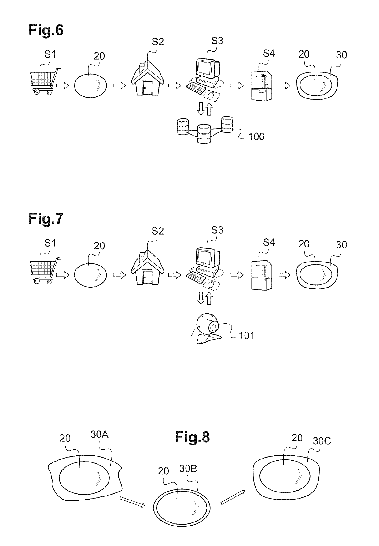
[0209]In a second embodiment, we can consider a wearer who wants to change his lenses 20 while keeping his frame 10.

[0210]Here, as shown in FIGS. 6 and 7, the wearer has to order a pair of lenses 20. It may do this operation over the Internet, by visiting the lenses manufacturer website and by filling prescriptions fields (step S1).

[0211]Then, when he receives at home the lenses 20 corresponding to his prescriptions (step S2), he has to order joints that are able to help him to mount the lenses in his frame 10. Indeed, the lenses 20 have predefined shapes (for example elliptical) that do not correspond to the shape of the rims of his frame 10.

[0212]The wearer can visit a joint manufacturer website so as to order the joints 30 (step S3). To order these joints 30, he has to give information relative to his frame 10.

[0213]For instance, he can give the references of his frame 10, so that the joint manufacturer can retrieve in a database 100 the frame characteristics (FIG. 6).

[0214]Other...


PUM

PropertyMeasurementUnit
widthaaaaaaaaaa
massaaaaaaaaaa
elasticaaaaaaaaaa

Abstract

Disclosed is eyeglasses equipment (1) including a frame (10), and at least one ophthalmic lens (20) mounted into the frame. The equipment includes a colored interface (30) that is placed between the frame and the lens.

Description

TECHNICAL FIELD TO WHICH THE INVENTION RELATES[0001]The present invention relates in general to eyeglasses.[0002]The invention applies more particularly to an eyeglasses equipment including a frame and ophthalmic lenses mounted into the frame.[0003]The invention also relates to a method for providing an eyeglasses equipment to a wearer, including steps of selecting a frame, selecting ophthalmic lenses, and mounting said lenses into said frame.TECHNOLOGICAL BACKGROUND[0004]The technical part of the profession of an optician consists in mounting a pair of correcting ophthalmic lenses in an eyeglass frame selected by a wearer.[0005]This mounting comprises at least five main operations:[0006]acquiring the shape of a longitudinal profile representative of the shape of the outline of one of the surrounds of the selected eyeglass frame;[0007]order a lens in accordance with filter needs an / or compensation of vision defect of the wearer;[0008]centering the ophthalmic lens under consideration...

Claims


Application Information

Patent Timeline
Patent Type & Authority Patents(United States)
IPC IPC(8): G02C1/06G02C7/02B29D11/00B33Y80/00
CPCG02C1/06B29D11/00432G02C7/02B33Y80/00G02C13/001B29D12/02B29D11/00009
Inventor ANATOLE, VINCENTMARTIN, GUILLAUMEMILLER, PHILIPKEITA, GABRIELGELLY, GERARDGUILLY, VINCENTDROBE, BJORN
Owner ESSILOR INT CIE GEN DOPTIQUE
Why Eureka
Try Eureka