Image display apparatus

a technology of image display and display screen, which is applied in the direction of discharge tube/lamp details, discharge tube/lamp details, cathode ray tube/electron beam tube, etc., can solve problems such as color drift, and achieve the effect of energy loss and improved image quality

Inactive Publication Date: 2006-02-23
CANON KK
View PDF11 Cites 2 Cited by
  • Summary
  • Abstract
  • Description
  • Claims
  • Application Information

AI Technical Summary

Benefits of technology

[0016] According to the above configuration, because the energy loss becomes sufficiently large when the scattered electro

Problems solved by technology

When the scattered electrons are incident to the adjacent pixel again, a phenomenon called halation in which the scattere

Method used


Image

  • Image display apparatus
  • Image display apparatus
  • Image display apparatus

Examples


example

[0041] Then, the invention will be described in detail based on specific examples.

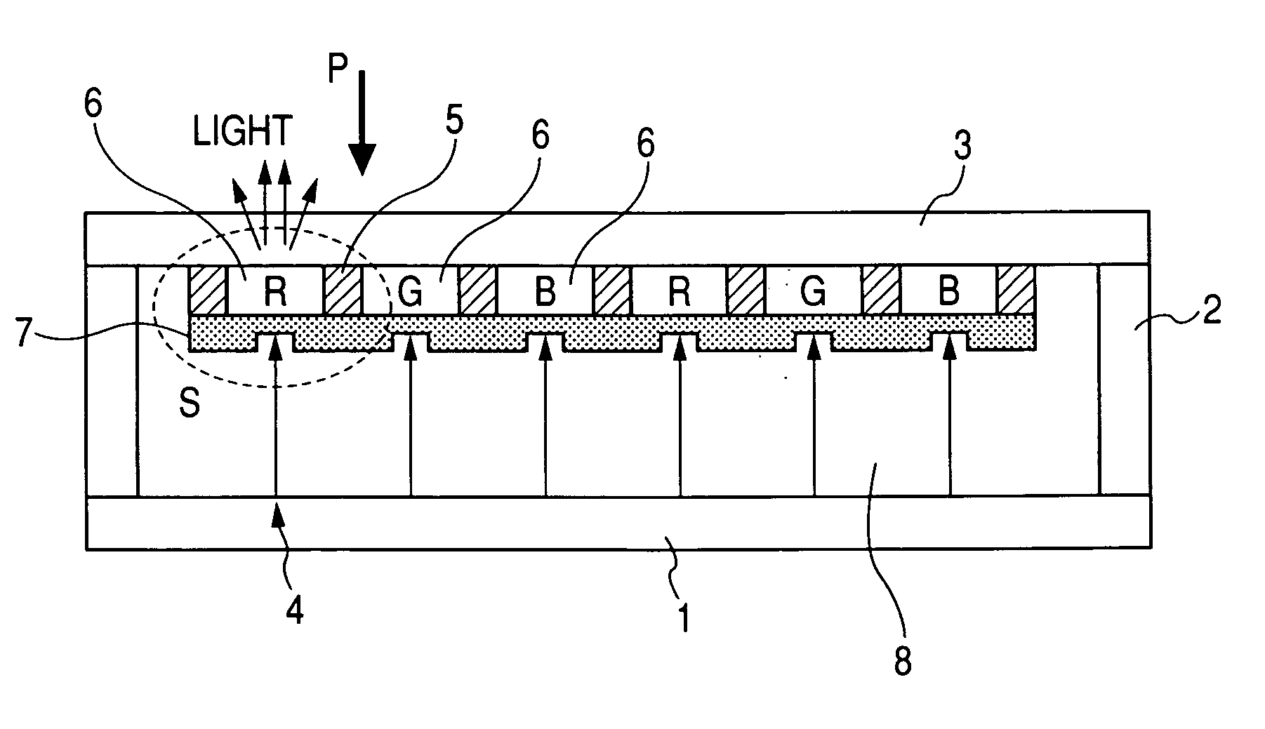
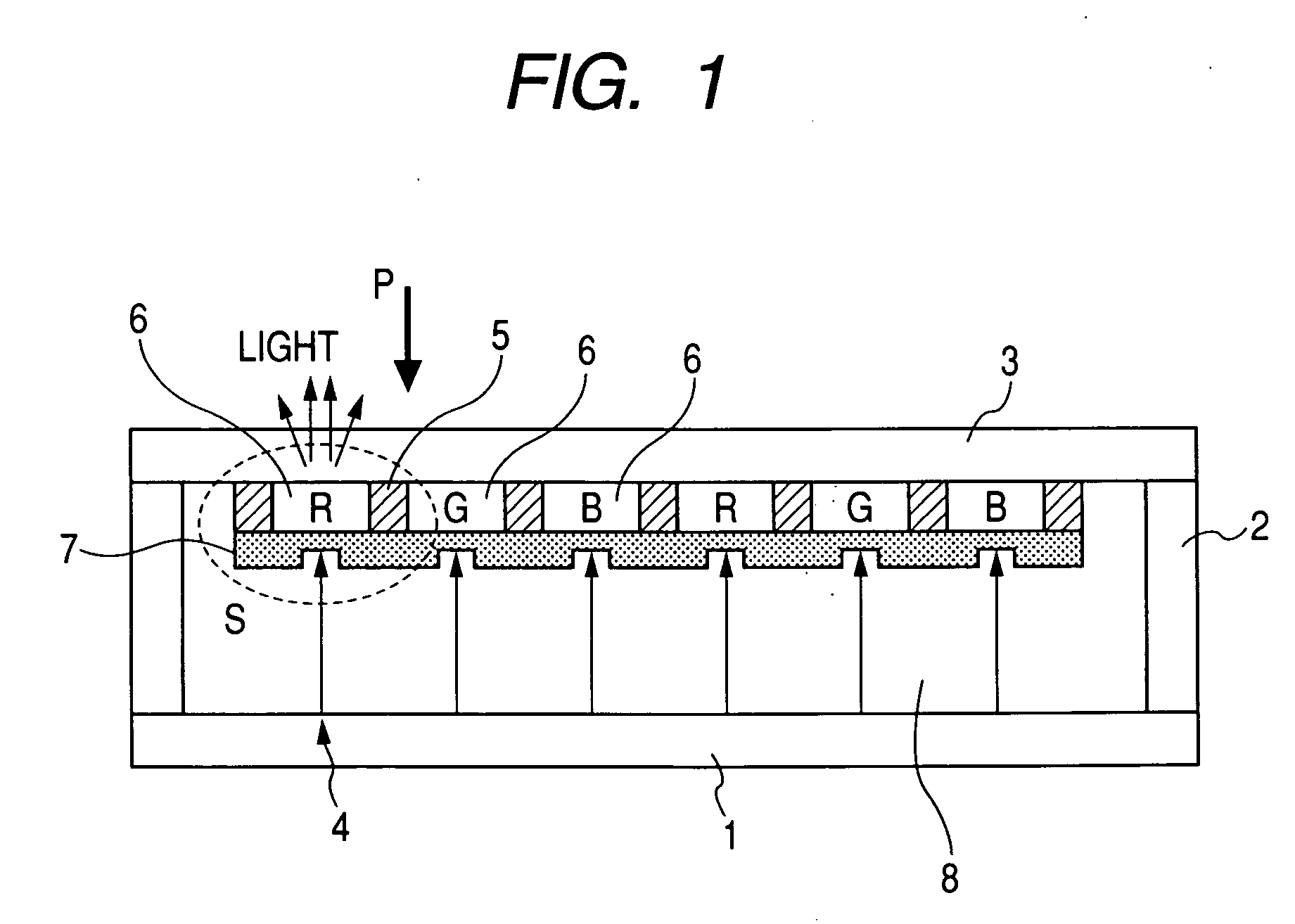
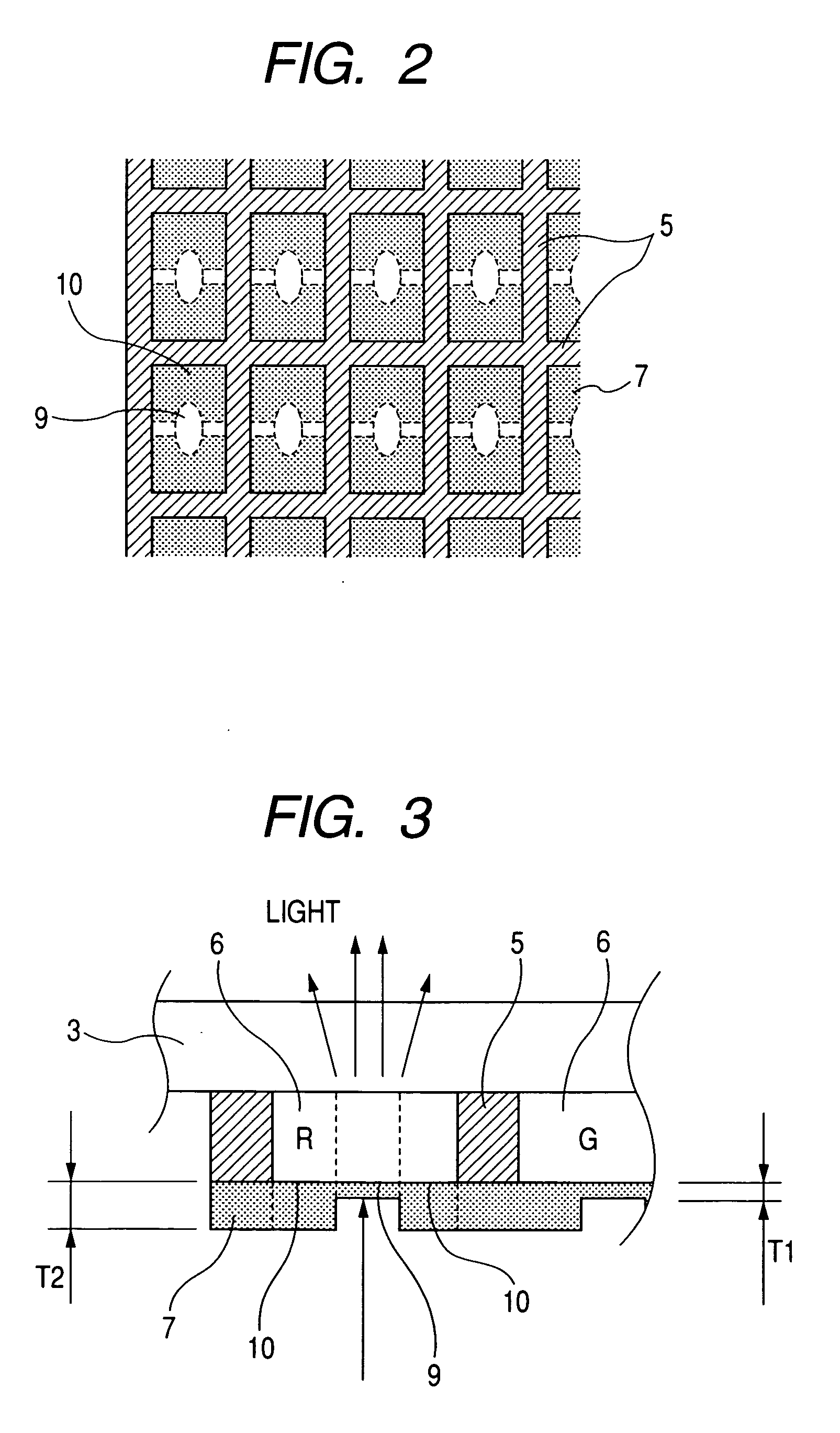
[0042] At first, the electron energy possessed by the electron emitted from the electron-emitting device 4 when the electron is incident to the phosphor member 6 and the electron energy possessed by the scattered electron when the scattered electron is incident to the phosphor member 6 will be described in the configuration in which an accelerating electrode X is arranged instead of the accelerating electrode 7 according to the embodiment. The thickness of the accelerating electrode X made of aluminum is constant independently of the center portion and the peripheral portion. In the case where the thickness of the accelerating electrode X and the voltage applied to the accelerating electrode X are appropriately changed, Table 1 shows the electron energy possessed by the electron emitted from the electron-emitting device 4 when the electron is passed through the accelerating electrode X to be incident ...


PUM


Abstract

In an image display apparatus in which an electron-emitting device is used, an image having high brightness and high contrast is formed while color drift is decreased to form the image having good color purity by suppressing halation. Assuming that a thickness is set at T1 in a portion corresponding to a center portion 9 of a phosphor member 6 and a thickness is set at T2 in a portion corresponding to a peripheral portion 10 of a phosphor member 6, a relationship of T1<T2 is met for the thickness of an accelerating electrode 7. Therefore, in the scattered electrons incident to the phosphor member 6 again, the scattered electron incident to the peripheral portion 10 of the phosphor member 6 has the large energy loss when the scattered electron is transmitted through the accelerating electrode 7, and halation brightness is decreased in the whole of the phosphor member 6. In the accelerating electrode 7, because the thickness T1 of the portion corresponding to the center portion 9 of the phosphor member 6 is kept thin, the electron energy possessed by the electron emitted from the electron-emitting device 4 when the electron is incident to the phosphor member 6 is kept high. Accordingly, the brightness of the bright spot is not decreased.

Description

BACKGROUND OF THE INVENTION [0001] 1. Field of the Invention [0002] The present invention relates to a structure of an image display apparatus which forms an image with an electron-emitting device. [0003] 2. Related Background Art [0004] In this type of image display apparatus, an electron emitted from an electron-emitting device is transmitted through an accelerating electrode which accelerates the electron, and a phosphor member made of a fluorescent material and the like is irradiated with the electron. In the phosphor member, a bright spot (light-emission spot) is generated in a region irradiated with the electron, and the image is formed by the plural bright spots (hereinafter sometimes individual phosphor member is referred to as pixel). [0005] However, the electrons with which the phosphor member is irradiated are scattered on the phosphor member (hereinafter the electron is referred to as “scattered electron”). When the scattered electrons are incident to the adjacent pixel ...

Claims


Application Information

Patent Timeline
IPC IPC(8): H01J1/62H01J63/04
CPCH01J29/085
Inventor SHIOYA, YASUSHI
Owner CANON KK
Why Eureka
Try Eureka