A spacer for camera lens with reduced flare phenomenon and manufacturing method thereof

A phenomenon and camera technology, applied in the field of spacers for camera lenses, which can solve the problems of overall image blurring and limited halo prevention, and achieve the effects of preventing peeling, reducing halo phenomenon, and blocking halo phenomenon.

Active Publication Date: 2019-07-02
可元株式会社
View PDF7 Cites 2 Cited by
  • Summary
  • Abstract
  • Description
  • Claims
  • Application Information

AI Technical Summary

Problems solved by technology

[0006] However, in the spacer using such a plastic material film base material, the film base material is exposed on the surface of the hollow portion during the process of forming the hollow portion, so there is a problem that the following halo phenomenon occurs: the light entering through the lens is reflected on the film base material. The exposed surface of the material is reflected, and a circular outline appears around a high-brightness object such as the sun that appears on the captured image, or the captured image is blurred like fog, etc.
However, since reflection of light cannot be avoided in the rest of the area that does not contain the surface anti-reflection beads, it is limited in preventing the halo phenomenon.

Method used


Image

  • A spacer for camera lens with reduced flare phenomenon and manufacturing method thereof
  • A spacer for camera lens with reduced flare phenomenon and manufacturing method thereof
  • A spacer for camera lens with reduced flare phenomenon and manufacturing method thereof

Examples


Embodiment 1

[0069] 1. First, mix the polyurethane series resin, the isocyanate series curing agent, and the retarder that hinders the intense reaction between the curing agent and the resin at a fixed ratio, and stir it at a speed of about 500 RPM for more than 30 minutes to prepare A primer solution was formed, and the primer solution was coated on a PET film substrate with a thickness of 0.25 μm for the first time.

[0070] At this time, as a coating method, microgravure coating, which can coat a film of 1 μm or less and has a relatively small thickness variation, is used as a method in which the solution filled in the mesh gap of the screen roll is transferred to the film and coated. Method (Micro Gavure Coating). In this embodiment, M200 Mesh produced by Media Engineering is used.

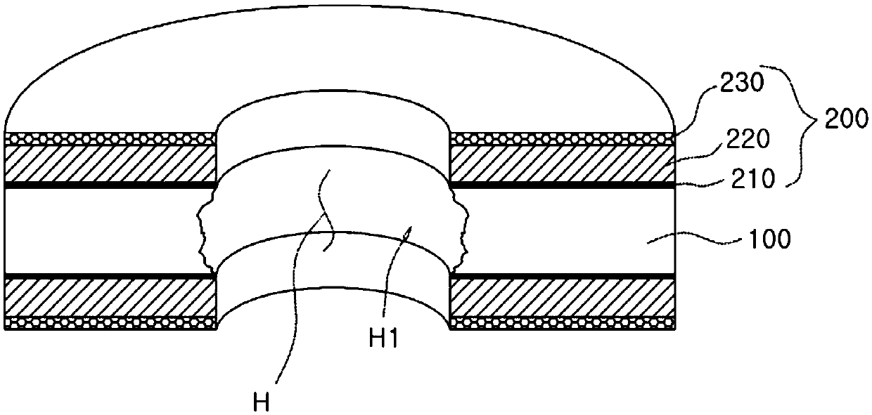
[0071] 2. Next, apply a functional coating on the surface of the base coat for the second time with a thickness of about 4 μm to form a black coating (220) by micro-gravure coating. The functional coating...


PUM


Abstract

The present invention relates to a spacer for a camera lens with reduced flare phenomena, eroding the inner surface of a hollow of a film substrate to prevent reflection of light; and a manufacturingmethod thereof. According to the present invention, the spacer comprises: the film substrate made of a plastic material; and a light blocking layer coated on both surfaces of the film substrate. The light blocking layer includes: a primer layer primarily coated to increase a bonding force of the surface of the film substrate; and a black coating layer coated on a surface of the primer layer as 10to 25 parts by weight of a lubricant, 3 to 5 parts by weight of a black oily dye, and 200 to 300 parts by weight of an organic solvent are mixed with respect to 100 parts by weight of a urethane-basedbinder. Moreover, the hollow is formed to penetrate the film substrate and the light blocking layer to allow light to be advanced towards a camera lens, wherein the inner surface of the hollow of thefilm substrate inducing a flare phenomenon is eroded by alkaline solution. Moreover, the manufacturing method thereof comprises: a primary coating step of forming the primer layer; a secondary coating step of forming the black coating layer; a perforating step; an erosion step of eroding the inner surface of the hollow of the film surface; and a drying step.

Description

technical field [0001] The present invention relates to a spacer for a camera lens with reduced halation and a manufacturing method thereof. More specifically, it relates to a spacer for a camera lens with reduced halo phenomenon and a manufacturing method thereof by etching the inner surface of a hollow portion of a film base material to minimize reflection of light. Background technique [0002] In recent years, smartphones with networked functions have become popular, starting with the popularity of camera phones, a new concept of mobile phones that combine digital camera technology and mobile phone technology. [0003] The miniaturization and weight reduction of camera modules such as mobile phone cameras, compact cameras, and video cameras are continuously progressing. In response, light-shielding members such as shutters, apertures, and spacers, which are mainly made of metal, are being replaced by light polymers. membrane instead. [0004] Here, a spacer is made by ...

Claims


Application Information

Patent Timeline
Patent Type & Authority Applications(China)
IPC IPC(8): G03B11/04G02B7/02
CPCG02B7/02G03B11/04G03B17/12
Inventor 李承翰
Owner 可元株式会社
Why Eureka
Try Eureka