
Glide rail

a technology of guide rails and rails, which is applied in the direction of rod connections, positive displacement liquid engines, machine supports, etc., can solve the problems of high initial installation costs, difficult transportation, and waste of excess piping, so as to reduce the useful life of guide rails and increase replacement costs

Inactive Publication Date: 2019-07-09
BRYX GRP LLC
View PDF50 Cites 2 Cited by
  • Summary
  • Abstract
  • Description
  • Claims
  • Application Information

AI Technical Summary

Benefits of technology

The text explains the disadvantages of using pipes for guiding submersible pumps in utility vaults, such as high installation and replacement costs and the decreased useful life of guide rails due to changes in the industry. Additionally, the text mentions the issue of hydrogen sulfide gas causing faster deterioration of traditional pipes, which requires more frequent replacement. The technical effect of this patent text is to provide a solution to address these issues and reduce costs associated with using pipes for guiding submersible pumps.

Problems solved by technology

A disadvantage in using these types of pipes is the cost and waste associated with their use.
As such, each 20-foot section of 2-inch pipe must be cut to meet this requirement, which results in wasted excess piping.
Another disadvantage of pipes is that they are often difficult to transport and require special means of transportation, which adds to the costs of using pipes as rails.
In particular, since pipes are often provided in a standard 20-foot length, it is difficult to transport the pipes in the bed of a standard work truck.
A third disadvantage of pipes is the cost for their initial installation as well as the cost of their replacement.
As explained above, the initial costs of installation are high due, in large part, to the wasted excess pipe.
Also, recent changes in the industry have led to a decreased useful life for guide rails, which has increased the replacement costs.
Hydrogen Sulfide gas is known to cause more rapid deterioration of traditional pipes, which has required that the pipes be replaced more often than was traditionally required.
This has resulted in substantial additional costs associated with the use of pipes as guide rails for submersible pump systems.

Method used


Image

  • Glide rail
  • Glide rail
  • Glide rail

Examples


Embodiment Construction

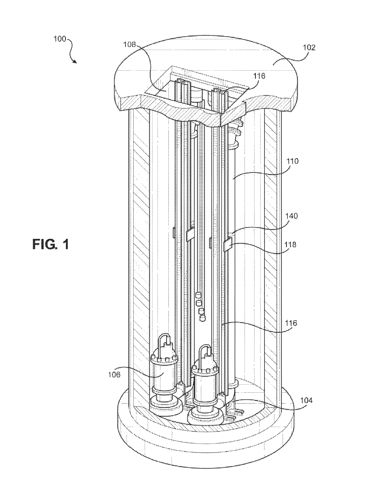
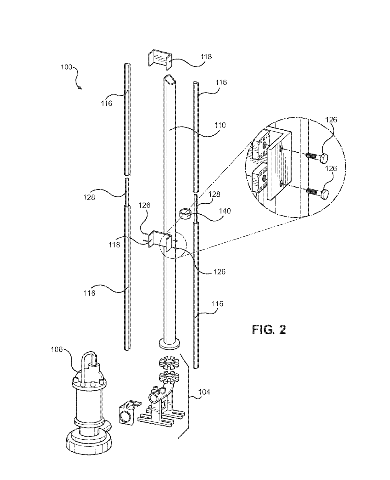
[0021]Referring now to the drawings in which like reference characters designate like or corresponding characters throughout the several views, there is shown in FIGS. 1 and 2, a submersible pump system 100 according to an embodiment of the present invention. The pump system 100 includes a concrete utility vault 102 having a top and bottom end. Utility vaults 102 of this type are often used for storing and conveying of sewage or waste water. Pumps 106 are often permanently mounted in the utility vault 102 and automatically cycle to pump sewage or waste water through a network of pipes to a municipal or industrial pollution control or waste water treatment facility. It may be necessary to periodically remove these pumps for required maintenance, replacement or upgrades etc., submersible pump system 100 allows for the safe removal and replacement of pumps 106 without the requirement of service personnel entering the utility vault 102. This design reduces or eliminates the confined spa...


PUM


Abstract

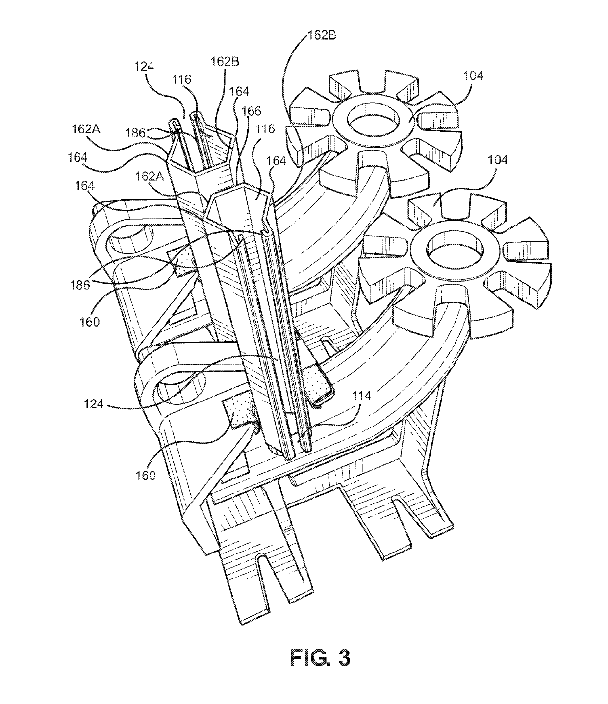
A submersible pump system including a pump base with a rail mounting point, a submersible pump configured to mate with to the pump base and to glide along a guide rail mounted to the rail mounting point, and a guide rail, made from one or more connected guide rail sections, defining a polygon shape and including a slot that extends between top and bottom ends of the guide rail. Brackets for connecting the guide rail to a vault may be attached to the slot of the rail. Additional mounting brackets or accessories may also be attached to the slot. The pump glides along the rail from the top of the vault to the bottom of the vault and automatically mates with the pump base.

Description

CROSS-REFERENCE TO RELATED APPLICATIONS[0001]This application claims the benefit of U.S. Provisional Application No. 62 / 036,246, filed Aug. 12, 2014 and entitled Glide Rail, the disclosure of which is incorporated by reference herein in its entirety.FIELD OF THE INVENTION[0002]This invention relates to the field of submersible pump systems. More particularly, this invention relates to a guide rail used in connection with an underground submersible pump system.BACKGROUND AND SUMMARY[0003]Various submersible pump systems are available for use in underground and other types of utility vaults. Some of these systems utilize two round pipes placed side-by-side as guide rails for raising and lower the pump into the vault. One end of these pipes is mounted to the top of pump bases and the opposing end is mounted to an opening at the top of the vault. The rails are inserted into guides located in the sides of the pump. When the pump is raised or lowered, the receiver glides along the rails. ...

Claims


Application Information

Patent Timeline
Patent Type & Authority Patents(United States)
IPC IPC(8): F16M13/02E03F5/22F04B23/02
CPCE03F5/22F16M13/02F04B23/021F04B23/04F16B7/0433F16B7/187F16B17/008
Inventor WOOTTEN, JOHN MARK
Owner BRYX GRP LLC
Learn More