Projection system, projection method, and projection program

a projection system and projection method technology, applied in the direction of picture reproducers using projection devices, static indicating devices, instruments, etc., can solve the problems of affecting the convenience of use, affecting the effect of use, and hardly projecting suitable images on uneven projection surfaces, so as to eliminate the effect of eliminating the shape and color of the detected obj

Active Publication Date: 2019-07-09
OPTIM
View PDF11 Cites 1 Cited by
  • Summary
  • Abstract
  • Description
  • Claims
  • Application Information

AI Technical Summary

Benefits of technology

[0006]An objective of the present invention is to provide a projection system, a projection method, and a projection program that improve the convenience.
[0010]an image correction unit that corrects an image to be projected so as to eliminate the shape of the detected object; and
[0014]The second aspect of the present invention provides the projection system according to the first aspect of the present invention, further including a color detection unit that detects the color of an object existing on the imaged projection surface by image analysis, in which the image correction unit corrects an image to be projected so as to eliminate the shape and the color of the detected object.
[0015]According to the second aspect of the present invention, the projection system according to the first aspect of the present invention detects the color of an object existing on the imaged projection surface by image analysis and corrects an image to be projected so as to eliminate the shape and the color of the detected object.
[0023]correcting an image to be projected so as to eliminate the shape of the detected object; and
[0028]correct an image to be projected so as to eliminate the shape of the detected object; and

Problems solved by technology

Thus, there is a problem in that the projection device hardly projects suitable images on uneven projection surfaces and distorts images on a distorted projection surface with an object.
This problem hampers the convenience.

Method used


Image

  • Projection system, projection method, and projection program
  • Projection system, projection method, and projection program
  • Projection system, projection method, and projection program

Examples


Embodiment Construction

[0037]Embodiments of the present invention will be described below with reference to the attached drawings. However, these are illustrative only, and the technological scope of the present invention is not limited thereto.

Overview of Project System 1

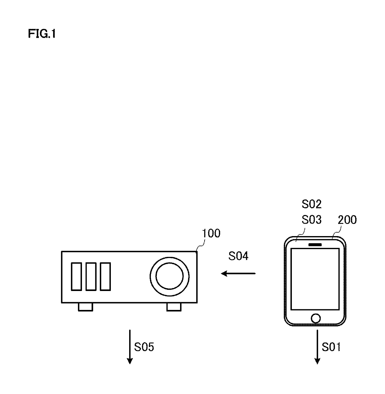
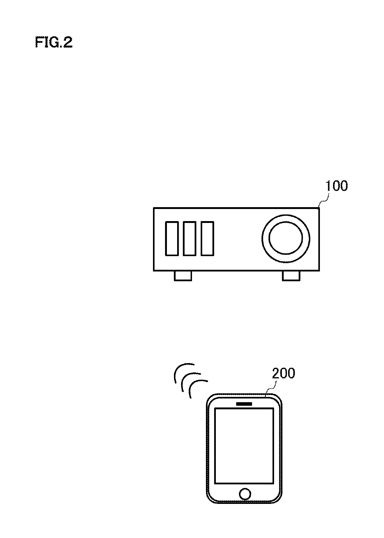
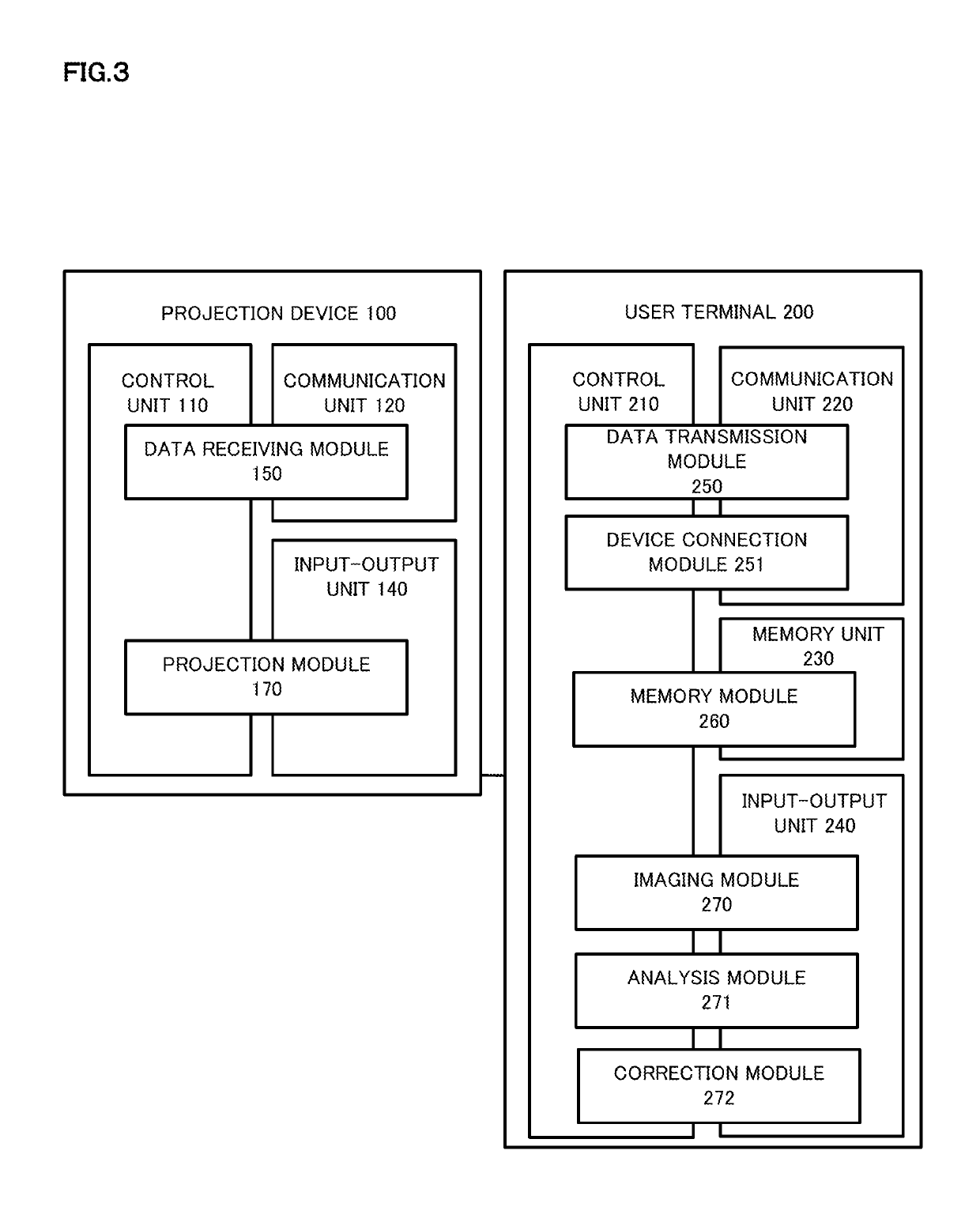
[0038]A preferable embodiment of the present invention will be described below with reference to FIG. 1. FIG. 1 shows an overview of the project system 1 according to a preferable embodiment of the present invention. The projection system 1 includes a projection device 100 and a user terminal 200. In FIG. 1, the numbers of the projection devices 100 and the user terminals 200 are not limited to one and may be two or more. The process to be described later may be achieved by either or both of the projection device 100 and the user terminal 200.

[0039]The projection device 100 is capable of data communication with the user terminal 200, which is a projection instrument such as a projector that is capable to project images on the projection ...


PUM


Abstract

The present invention is to provide a projection system, a projection method, and a projection program that improve the convenience. The projection system 1 that corrects an image to be projected on a projection surface images the projection surface, detects the shape of an object existing on the imaged projection surface by image analysis, corrects an image to be projected so as to eliminate the shape of the detected object, and projects the corrected image on the projection surface.

Description

TECHNICAL FIELD[0001]The present invention relates to a projection system, a projection method, and a projection program that project images on a projection surface.BACKGROUND ART[0002]Recently, projection devices such as projectors that project images on the projection surfaces of walls and screens have been widespread. Such projection devices also project images on the surface of other things than screens. For example, projection devices project images on the projection surfaces of ceilings, walls, and floors.[0003]Among such projection devices, the projection device that projects suitable images on a projection surface by receiving the input that changes image shape data to be projected according to the unevenness of the projection surface (see Patent Document 1).CITATION LISTPatent Literature[0004]Patent Document 1: JP 2014-233056 ASUMMARY OF INVENTION[0005]However, the projection device of Patent Document 1 requires the user to input image shape data. Thus, there is a problem i...

Claims


Application Information

Patent Timeline
Patent Type & Authority Patents(United States)
IPC IPC(8): G03B21/14G06T7/50G02B27/00H04N9/31G06F3/0484
CPCG03B21/147G02B27/0043H04N9/3185G06T7/50H04N9/3182G06F3/0484H04N9/3194G09G3/001G09G2320/0233G09G2320/0242G09G2320/0693G03B17/54G09G5/00G03B21/14
Inventor SUGAYA, SHUNJI
Owner OPTIM
Why Eureka
Try Eureka