
Method of automatically setting a welding parameter for MIG/MAG welding and a controller for performing the method

a technology of mig/mag welding and automatic setting, which is applied in the direction of welding apparatus, arc welding apparatus, manufacturing tools, etc., can solve the problems of difficult control, high risk of weld spatter and weld smoke, and inability to stabilize the arc, so as to facilitate the welding of different weld cases and reduce the number of factors

Active Publication Date: 2019-07-16
ESAB AB
View PDF52 Cites 3 Cited by
  • Summary
  • Abstract
  • Description
  • Claims
  • Application Information

AI Technical Summary

Benefits of technology

[0013]It is an object of the invention to facilitate welding of different weld cases by reducing the number of factors that must be accounted for when initiating a welding process.
[0025]By use of the method of automatically setting a welding parameter for MIG / MAG welding according to the invention, the need for setting a wire feed speed manually or by use of complex synergy lines reflecting the complete welding case is obviated and replaced by an automatic setting of the wire feed speed determined from a desired welding current. Optionally the desired welding current is automatically determined from an input from an operator selecting a thickness of the working piece. The complexity of setting welding conditions is thereby reduced.
[0029]By maintaining the percentage of the short-circuiting time in relation to the period time constant at the desired set value, a good effect on the tolerance of the welding towards different external influencing factors, such as variations in distance between a contact tip and the workpiece is obtained. The period time is the sum of the short-circuiting time and the arc time during a welding cycle.
[0036]The need of tested synergy lines for different electrode material, electrode dimension and shielding gas type will to a large extent not be needed any longer, and thus the security of a proper repetition accuracy during welding with wires and gases from different suppliers and from different manufacturing batches is increased.
[0039]An automatic detection of the welding wire material and welding wire dimension enables automatic determination of the globular area transition current. The proposed embodiment thus enables adjustment of the short-circuiting percentage from a first larger value to a second smaller value when said desired welding current is increased to a value equal or greater than the globular area transition current, and adjustment of the short-circuiting percentage from a second smaller value to a first larger value when the desired welding current is decreased to a value equal or smaller than the globular area transition current.

Problems solved by technology

The result is an unstable arc which is difficult to control with a risk for much weld spatter and weld smoke.
As a result of the mutual interference between the static and dynamic characteristics optimization of the process is difficult.
To select a suitable reference value for the voltage for a particular electrode speed may be difficult for a welding operator, since an appropriate reference value is dependent on such factors as electrode material, electrode dimension and shielding gas type.
In addition, the electrode quality may vary between different deliveries and thus lead to that previously tested synergy lines do not function any longer.
This also leads to problems in having a predetermined quantity of synergy lines suitable for all weld cases.
Obviously, this leads to a troublesome uncertainty when welding a new batch.

Method used


Image

  • Method of automatically setting a welding parameter for MIG/MAG welding and a controller for performing the method
  • Method of automatically setting a welding parameter for MIG/MAG welding and a controller for performing the method
  • Method of automatically setting a welding parameter for MIG/MAG welding and a controller for performing the method

Examples


Embodiment Construction

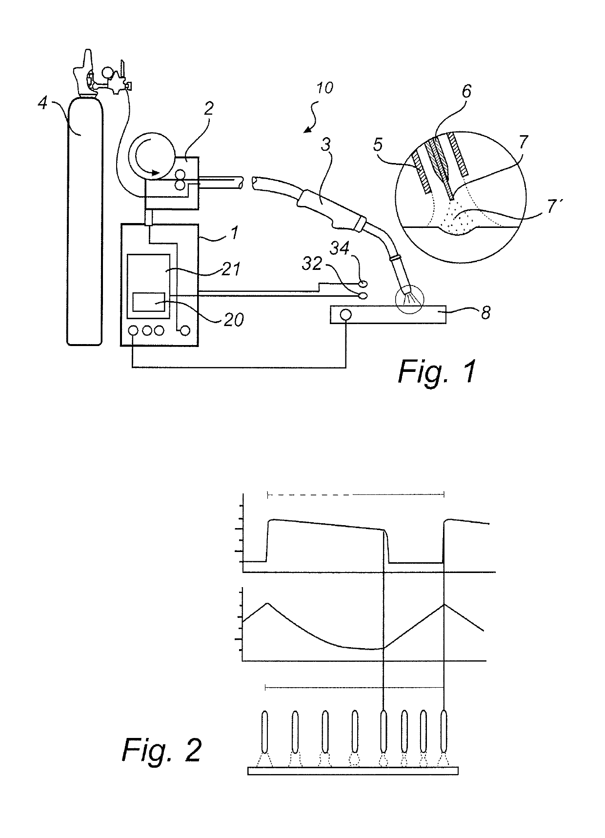
[0049]FIG. 1 discloses welding equipment for MIG / MAG welding. The welding equipment disclosed comprises a welding machine 10 having a power source 1 adapted to supply welding energy, or melting power, to the electrode 7. Preferably the power source 1 comprises an inverter power supply. An electrode feeder 2 is provided on the welding machine 10. The electrode feeder 2 is adapted to feed the electrode 7 to a welding torch 3. The welding torch 3 is connected to the electrode feeder 2, the welding machine 10 and a gas container 4 via a welding cable. The welding torch 3 comprises a gas cup 5 and a contact tube 6 through which the electrode 7 is fed to a position in the proximity of the workpiece 8. Welding gas is supplied from the gas container 4 to the space enclosed between the gas cup 5 and the contact tube 6.

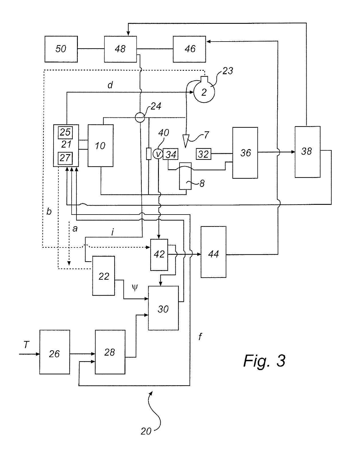
[0050]Furthermore, the welding equipment comprises a welding controller 20. The welding controller 20 includes a general controller 21 which is arranged to control the welding ...


PUM

PropertyMeasurementUnit
speedaaaaaaaaaa
feed speedaaaaaaaaaa
thicknessaaaaaaaaaa

Abstract

A method of automatically setting a welding parameter for MIG / MAG welding including the following steps: initiating a parameter setting welding operation; detecting a response welding current at a present wire feed speed during the parameter setting welding operation; determining a first function mapping the response welding current to the set wire feed speed; determining a desired wire feed speed from the first function and the desired welding current.

Description

FIELD OF INVENTION[0001]The invention relates to a method of automatically setting a welding parameter for MIG / MAG welding. The invention furthermore relates to a welding method which is subdivided into a parameter setting welding operation where a welding test is performed in order to derive a welding parameter and a subsequent welding operation which is based on the welding parameter derived during the parameter setting welding operation. The invention also relates to a controller arranged for performing the method.BACKGROUND OF THE INVENTION[0002]MIG / MAG-welding is a welding process where an electrode is continuously fed toward a working piece. An electric power source generates a welding voltage and a welding current. During the welding process, the workpiece is heated primarily by an arc generated by the power source. The electrode is heated, partly by the power developed in the electrode as the weld current flows through an electrode stick out, and partly by the heat developed...

Claims


Application Information

Patent Timeline
Patent Type & Authority Patents(United States)
IPC IPC(8): B23K9/095
CPCB23K9/0956B23K9/0953B23K9/095B23K9/12B23K9/173
Inventor ABERG, PER
Owner ESAB AB
Learn More