Aircraft comprising a propulsion assembly including a pair of propellers at the rear of the fuselage

a propulsion assembly and fuselage technology, applied in the field of aeronautical, can solve the problems of total loss of thrust, total obstruction of hot inner flow, and inability to generate thrust, so as to maximise propulsion efficiency and maximize thermal efficiency

Active Publication Date: 2019-07-16
SN DETUDE & DE CONSTR DE MOTEURS DAVIATION S N E C M A
View PDF16 Cites 1 Cited by
  • Summary
  • Abstract
  • Description
  • Claims
  • Application Information

AI Technical Summary

Benefits of technology

[0016]Given that the two motors drive the motor shafts at the same speed with the same torque, this system makes it possible to supply power coming from two sources with potential but relatively low variations in speed or torque provided, to a single output shaft. This shaft is then connected to a differential train, making it possible to distribute the torque across the two propellers.
[0020]The aim of spacing apart the air input ducts is, in particular, to avoid the ingestion of the boundary layer of the air flowing along the fuselage by the motors, avoiding disturbances associated with them which are disadvantageous in terms of the thermal efficiency of the motor.

Problems solved by technology

In the context of such a solution, the ability to generate thrust may not be maintained in the event of failure of the part of the propulsion system made up of the counter-rotating turbine and the counter-rotating fans.
For example, in the event of destruction of the blades of the counter-rotating turbine, a total obstruction of the hot inner flow may be caused by the debris.
This would result in the total loss of thrust and a high pumping probability of the gas generators due to the sudden change in the flow cross-section.
In addition, the installation method of the gas generators being fully integrated into the fuselage assumes an arrangement of air inputs that makes it possible to not supply the generators with the boundary layer developed on the fuselage of the aircraft; the fact that this has a speed which is substantially slower than the flying speed is detrimental to the thermal efficiency of the gas generators.
In particular, the problem presented concerns the drive of the pair of propellers by a motor assembly which is likely to have speed and torque variations within a certain operating margin.

Method used


Image

  • Aircraft comprising a propulsion assembly including a pair of propellers at the rear of the fuselage
  • Aircraft comprising a propulsion assembly including a pair of propellers at the rear of the fuselage
  • Aircraft comprising a propulsion assembly including a pair of propellers at the rear of the fuselage

Examples


Embodiment Construction

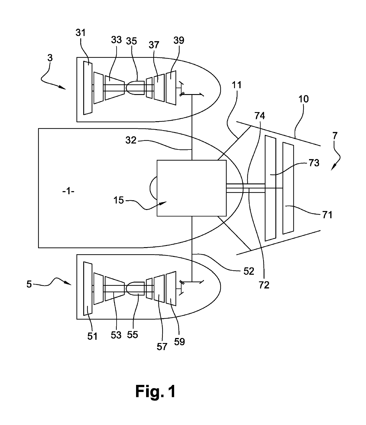
[0028]The propulsion assembly is mounted at the rear of the aircraft, of which the rear part of the fuselage 1 has been shown. The two gas motors 3 and 5 are mounted on this fuselage having a longitudinal axis X by means of pylons which are arranged appropriately but are not shown. These two pylons are positioned in such a way as to set aside sufficient space between the wall of the fuselage 1 and the air input duct of each of the motors 3 and 5, thus preventing the air of the boundary layer formed along the fuselage from being directed towards the air input ducts. This air flows along the fuselage towards the rear.

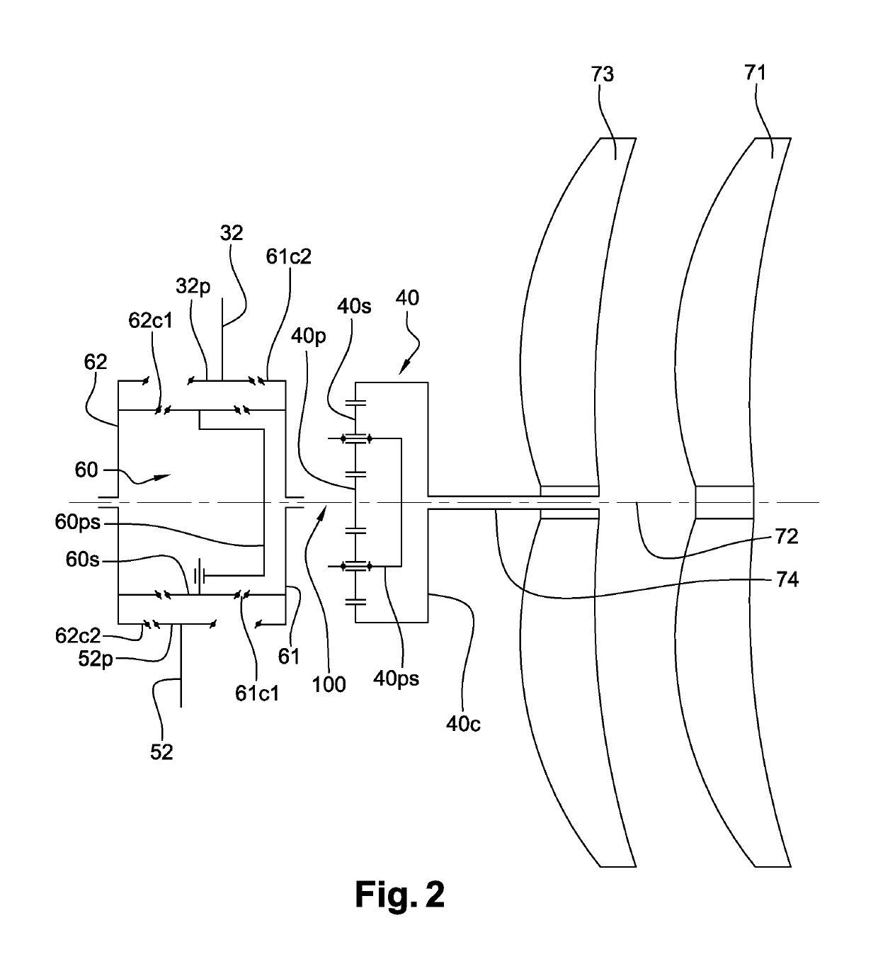
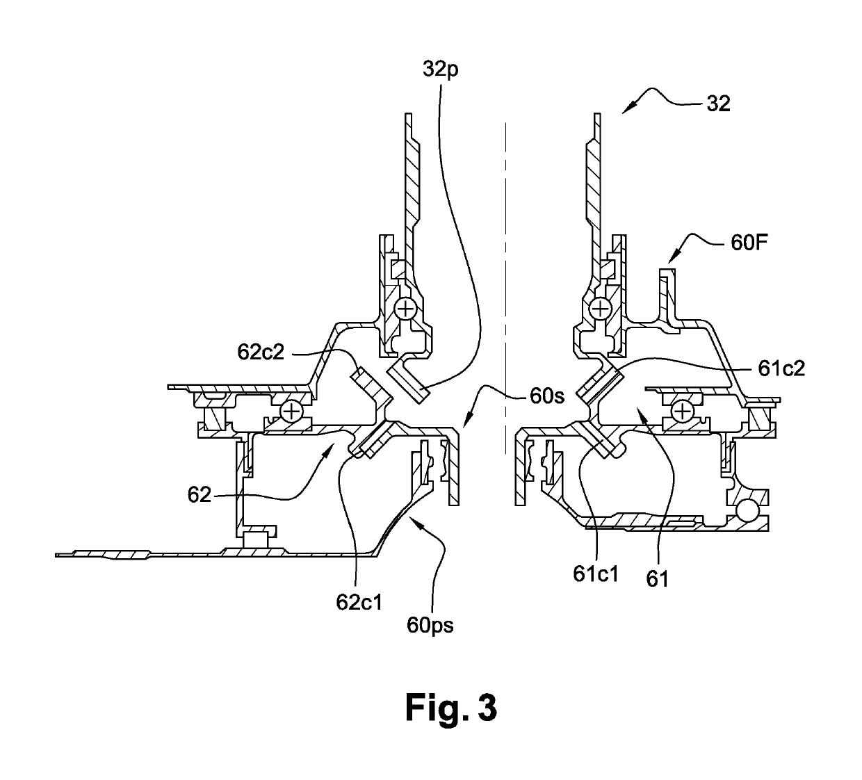
[0029]The motors are turbojets in the example illustrated here. They thus comprise a low-pressure body formed of a rotor with a compressor 31; 51 and a turbine 39; 59, and a high-pressure body formed of a rotor with a compressor 33; 53 and a turbine 37; 57. The compressors power a combustion chamber 35; 55, the gas products of which drive the high-pressure and low-pressur...


PUM


Abstract

The present invention relates to an aircraft comprising a fuselage (1), a propulsion unit (7) at the rear tip of the fuselage and at least two engines (3, 5) each driving an engine shaft (32, 52), the propulsion unit including at least one propeller (71, 73) driven mechanically by the engine shafts (32, 52), characterized in that the propulsion unit (7) includes two propellers (71, 73), each of the propellers being driven by a propeller shaft (72, 74), the two propeller shafts being driven by the engine shafts (32, 52) via a first differential epicyclic gear train (40). Specifically, the input of the first differential gear train (40) is connected to the output of a second differential epicyclic gear train (60), the second differential gear train (60) including two inputs (61c2, 62c2), each of said two inputs being connected mechanically to one of said engine shafts (32, 52).

Description

FIELD OF THE INVENTION[0001]The present invention relates to the aeronautical field in which aircraft are propelled at least in part by a fan rotor assembly positioned at the rear in the extension of the fuselage. The fan rotors are driven by motors such as turbojets.PRIOR ART[0002]A new aircraft architecture was proposed in the patent application FR-A1-2 997 681, making it possible to reduce noise pollution and fuel consumption of the aircraft by limiting aerodynamic drag.[0003]In the context of such an architecture, an aircraft is propelled by a propulsion system with counter-rotating fans, integrated into the rear of the fuselage of the aircraft, in the extension thereof. The propulsion system comprises two gas generators which supply a power turbine having two counter-rotating rotors for driving two fan rotors, the fans being positioned downstream of the gas generators. The gas generators are gas turbine engines incorporated into the fuselage with separate air inputs that each s...

Claims


Application Information

Patent Timeline
Patent Type & Authority Patents(United States)
IPC IPC(8): B64D35/06F02K3/072F02C7/36B64C11/48B64D27/14B64D33/02F16H48/10B64D35/08F16H48/05F16H48/08
CPCB64D27/14B64C11/48B64D33/02B64D35/06B64D35/08F02K3/072F16H48/05F16H48/08F16H48/10F02C7/36F05D2260/40311F05D2220/323
Inventor REIGNER, PIERRE-ALAIN JEAN PHILIPPEBEAUJARD, ANTOINE JEAN-PHILIPPECURLIER, AUGUSTIN MARC MICHEL
Owner SN DETUDE & DE CONSTR DE MOTEURS DAVIATION S N E C M A
Why Eureka
Try Eureka