Analyzing-device controller

a technology of analyzing device and controller, which is applied in the direction of measurement device, scientific instruments, instruments, etc., can solve the problems of increasing complexity of analysis conditions, waste of specimens, and practically useless analysis, so as to reduce the use of specimens, improve the efficiency of analysis tasks, and reduce the effect of mobile phase and other consumed substances

Inactive Publication Date: 2019-07-23
SHIMADZU CORP
View PDF11 Cites 0 Cited by
  • Summary
  • Abstract
  • Description
  • Claims
  • Application Information

AI Technical Summary

Benefits of technology

[0032]With the analyzing-device controller according to the present invention, it is possible to avoid the situation that an analysis for a specimen is performed using an analysis method that does not correspond the target compound in the specimen concerned. Useless analyses are thereby prevented, so that the analysis time is shortened and the efficiency of the analyzing task is improved. The use of the specimen, mobile phase and other consumed substances can be decreased, whereby the cost of the analysis can be reduced. The fact that the operator in charge of the task does not need to have a high amount of expertise on the analysis is also advantageous for the cost reduction of the analysis. Incorrect operations or similar errors which cause a delay in the analyzing task or provision of an inappropriate result can also be prevented.

Problems solved by technology

In recent years, with the improvements in the performance and functions of analyzing devices, the analysis conditions have been increasingly complex, with a large number of items to be set by users in relation to those conditions.
However, in research institutes or contracted analysis businesses which need to perform measurements and analyses for an enormous number of samples, it is often the case that an operator with no expertise pertaining to the analyses and related tasks takes charge of the actual analyzing task.
Such an analyzing technique using a conventional analyzing device has the following problem.
Such an analysis is practically useless and merely wastes the specimen.
It is also a waste of time used for the analysis as well as a waste of mobile phase and carrier gas in the case of the LC or GC.
Furthermore, according to the previously described conventional technique, when a plurality of compounds whose quantities need to be determined are contained in one specimen, it is basically necessary to repeat a plurality of times the analysis for the same specimen using different analysis methods, so that the analysis requires a considerable amount of time.
However, since the detection process for the plurality of compounds needs be completed within the limited length of time during which the target compound is being eluted, the detection time per one compound becomes short, so that the sensitivity becomes low.
However, this method also results in a longer period of time required for one analysis; in some cases, the gradient analysis requires almost the same amount of time as the normal analysis performed two times for the same specimen.
Furthermore, an analysis method prepared for a gradient analysis is normally unusable for an analysis of a specimen containing other compounds; the analysis method is dedicated for a specimen containing a specific combination of compounds, and therefore, is unsuitable for an exhaustive analysis.
Needless to say, the task of preparing the analysis method is extremely complex and time-consuming.

Method used


Image

  • Analyzing-device controller
  • Analyzing-device controller
  • Analyzing-device controller

Examples


Embodiment Construction

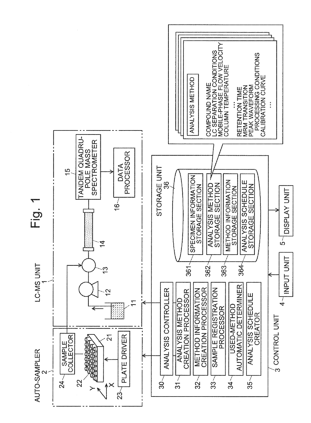
[0039]One embodiment of an LC-MS analyzing system using an analyzing-device controller according to the present invention is hereinafter described with reference to the attached drawings. FIG. 1 is a schematic configuration diagram of the LC-MS analyzing system according to the present embodiment.

[0040]This LC-MS analyzing system includes: a liquid chromatograph mass spectrometer unit (LC-MS unit) 1 which temporally separates the compounds contained in a sample solution (specimen) and detects those compounds; an auto-sampler 2 which sequentially selects one of a number of previously set vials 22 and supplies the sample solution from the selected vial 22 to the LC-MS unit 1; a control unit 3 which controls the operations of the aforementioned units; and other relevant units.

[0041]The LC-MS unit 1 includes: a mobile phase container 11 holding a mobile phase; a pump 12 for drawing the mobile phase from the mobile phase container 1 and supplying it at a substantially constant flow veloc...


PUM

PropertyMeasurementUnit
liquid chromatographaaaaaaaaaa
gas chromatographaaaaaaaaaa
mass spectrometeraaaaaaaaaa

Abstract

A specimen information storage section (361) holds specimen information showing the relationship between a number of specimens to be analyzed and compounds whose quantities need to be determined. An analysis method storage section (362) holds the files of analysis methods created by an administrator. When an operator selects and indicates analysis methods to be used in an analysis, a method information creation processor (32) extracts compound information from the selected analysis methods and creates method information showing the correspondence between the analysis methods and the compounds to be analyzed. When the operator registers the specimen numbers of the analysis targets, a used-method automatic determiner (34) refers to the specimen information and method information to identify a suitable analysis method for each compound in the registered specimens. An analysis schedule creator (35) creates a schedule table in which the specimens and analysis methods are described in order of the analysis. This schedule includes no useless analysis performed using an analysis method which is unsuitable for the analysis concerned. Consequently, the efficiency of the analysis is improved.

Description

CROSS REFERENCE TO RELATED APPLICATIONS[0001]This application is a National Stage of International Application No. PCT / JP2014 / 065549 filed Jun. 12, 2014, the contents of all of which are incorporated herein by reference in their entirety.TECHNICAL FIELD[0002]The present invention relates to a controller for an analyzing device, such as a liquid chromatograph, gas chromatograph, liquid chromatograph mass spectrometer, or gas chromatograph mass spectrometer and particularly, to a controller suitable for an automatic analyzing device which continuously performs an analysis for a plurality of samples using the combination of an auto-sampler which automatically selects and collects each sample from a number of prepared samples and an analyzing device which analyzes the sample collected with the auto-sampler.BACKGROUND ART[0003]In an analyzing device, represented by a liquid chromatograph (LC) or gas chromatograph (GC), an analysis for a sample is conducted according to preset analysis co...

Claims


Application Information

Patent Timeline
Patent Type & Authority Patents(United States)
IPC IPC(8): G01N30/88G01N30/86G01N30/24G01N35/00G01N30/72
CPCG01N30/88G01N30/24G01N30/86G01N35/0092G01N2035/0094G01N30/7233G01N2030/8804
Inventor MATSUO, KIRIKO
Owner SHIMADZU CORP
Why Eureka
Try Eureka