Selectable flow divider drive system

a drive system and flow divider technology, applied in the direction of fluid couplings, rotary clutches, couplings, etc., can solve the problems of large flow loss, engine stall, and compromise of flow division, so as to improve flow division and cost-effective

Active Publication Date: 2019-08-06
JLG IND INC
View PDF16 Cites 0 Cited by
  • Summary
  • Abstract
  • Description
  • Claims
  • Application Information

AI Technical Summary

Benefits of technology

[0007]The flow dividers according to preferred embodiments are sized for the low flow condition and are automatically or manually bypassed during high flow conditions. This arrangement allows for a more cost effective system as well as for improved flow division in low flow conditions, which is of particular importance for operation of an AWP.

Problems solved by technology

Otherwise, wheels could be forced to slide during turns or the engine could stall.
If this bypass is too large, the flow division is compromised as a large portion of the flow could be lost to leakage.
AWPs traditionally are designed with these traction valves sized for the high flow rate needed to achieve a max drive speed, which influences the efficiency and power requirements of not only high flow conditions but also low flow performance.

Method used


Image

  • Selectable flow divider drive system
  • Selectable flow divider drive system
  • Selectable flow divider drive system

Examples


Embodiment Construction

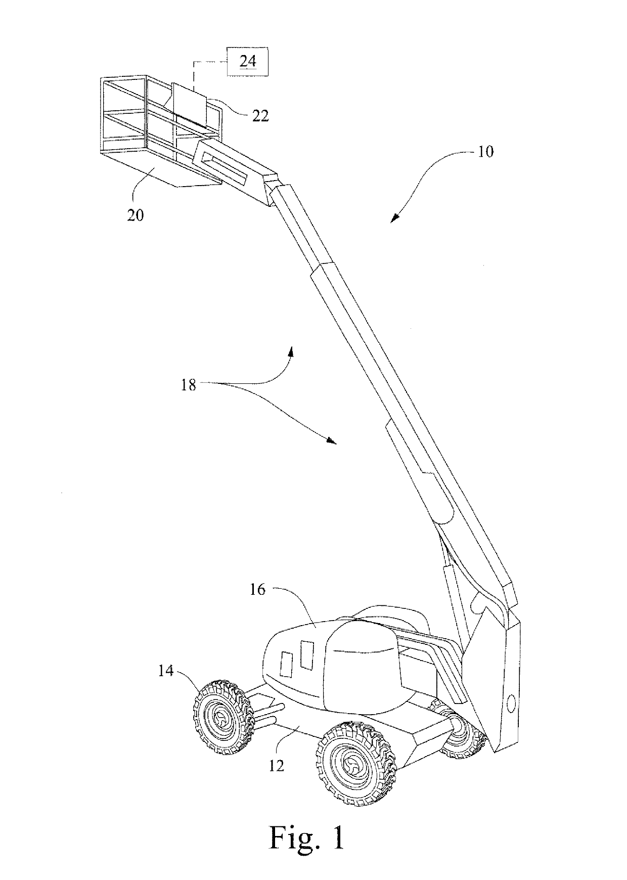
[0020]FIG. 1 shows an exemplary aerial work platform 10 for which the drive system of the invention is suitable. The machine 10 includes a chassis 12 supporting drive wheels 14. In the exemplary AWP shown, a turntable 16 is supported on the chassis 12. The turntable 16 supports a boom configuration 18, and a work platform 20 is supported at a distal end of the boom configuration 18. Operator controls 22 on the work platform 20 enable the operator to position the boom and drive the vehicle from the work platform 20. The operator controls 22 communicate with a control system 24 (shown schematically in FIG. 1) that controls operating parameters of the vehicle 10 based on input from the operator controls 22 as well as external sensors and operating conditions.

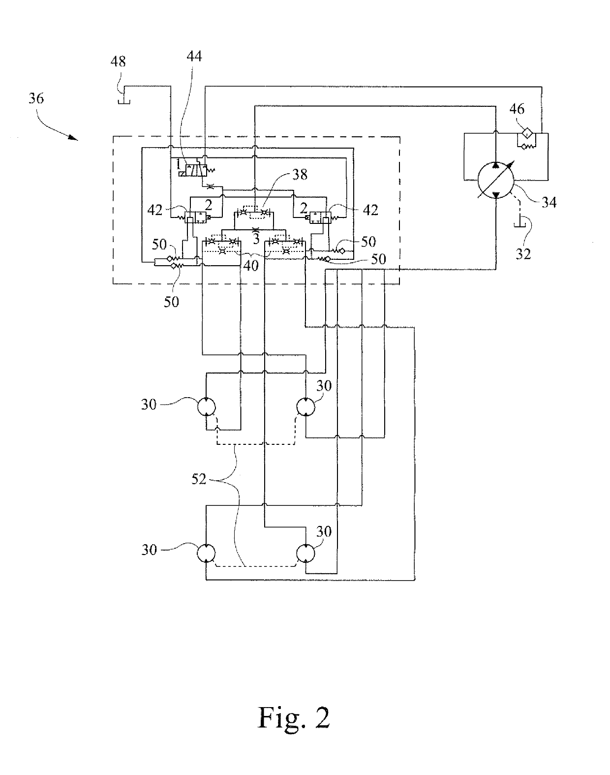
[0021]FIG. 2 is a schematic drawing of the selectable flow divider drive system for controlling drive functionality of the vehicle 10. A hydraulic motor 30 is associated with each wheel 14 for driving the wheel 14 in forward and re...


PUM


Abstract

A selectable flow divider drive system includes a hydraulic fluid reservoir and a plurality of drive motors in fluid communication with the hydraulic fluid reservoir. A hydraulic pump is connected between the hydraulic fluid reservoir and the plurality of drive motors and directs hydraulic fluid from the hydraulic fluid reservoir to the plurality of motors. The hydraulic pump is operable in a high flow condition and a low flow condition. A flow divider component is interposed between the hydraulic pump and the plurality of motors. The flow divider component selectively divides hydraulic fluid flow to each of the plurality of drive motors, where a flow divider of the flow divider component is sized for the low flow condition of the hydraulic pump. A bypass valve is disposed upstream of the flow divider that selectively bypasses the flow divider when the hydraulic pump is operated in the high flow condition.

Description

CROSS-REFERENCES TO RELATED APPLICATIONS[0001]This application is the U.S. national phase of International Application No. PCT / US2011 / 043002 filed 6 Jul. 2011 which designated the U.S. and claims priority to U.S. Provisional Patent Application No. 61 / 361,732 filed 6 Jul. 2010, the entire contents of each of which are hereby incorporated by reference.STATEMENT REGARDING FEDERALLY SPONSORED RESEARCH OR DEVELOPMENT[0002](Not Applicable)BACKGROUND OF THE INVENTION[0003]The invention relates to aerial work platforms and, more particularly, to a hydraulic drive system for an aerial work platform.[0004]Aerial Work Platforms (AWPs) typically use hydrostatic drives systems. They could be two- or four-wheel drive with a gear reduction and a hydraulic drive motor at each driven wheel. A hydraulic pump is typically driven directly from the engine and includes a network of traction valves or flow dividers to split the flow to each driven wheel. These flow dividers are intended to divide the tota...

Claims


Application Information

Patent Timeline
Patent Type & Authority Patents(United States)
IPC IPC(8): F15B13/02B60K7/00F16H61/4035F16H61/456B66F11/04B60K17/14
CPCF15B13/022B60K7/0015B66F11/04F16H61/456F16H61/4035B60W2720/30B60K17/14
Inventor SHADE, RICHARD A.
Owner JLG IND INC
Why Eureka
Try Eureka