Refiner plate segment with pre-dam

a technology of pre-dam and refiner plate, which is applied in the field of refiner plate, can solve the problems achieve the effects of reducing energy consumption, less wear, and longer useful li

Active Publication Date: 2019-08-13
VALMET AB
View PDF14 Cites 0 Cited by
  • Summary
  • Abstract
  • Description
  • Claims
  • Application Information

AI Technical Summary

Benefits of technology

[0007]By arranging a pre-dam, which has a height that is less than the height of a main dam, in front of a main dam, the flow of lignocellulosic material first encounters the pre-dam, and, since the height of the pre-dam is relatively less than the height of the main dam, the change of flow direction is relatively less pronounced when the material flow encounters a pre-dam than when the material flow encounters a main dam, as will be thoroughly explained and described below. The change of flow direction for the lignocellulosic material can be regarded as a “lift” from a radial movement within a groove to an additional movement into a refining gap provided between two opposing refiner plates, or, more specifically, between crossing bars provided on two opposing and rotating refiner plates. Because of this lift, which has already been achieved by a pre-dam, the material flow will encounter a main dam at angle which is less than a perpendicular angle, which causes less wear on the main dam and thereby contributes to a longer useful lifetime for the refiner plate segment. The relatively smoother change of flow direction reduces the impact of the main dam on the material flow and leads to a decreased energy consumption. The change of flow direction is also less abrupt and more controlled when a pre-dam is arranged in front of a main dam, which leads to an improved flow distribution, which, in turn, improves fiber quality.

Problems solved by technology

The relatively smoother change of flow direction reduces the impact of the main dam on the material flow and leads to a decreased energy consumption.

Method used


Image

  • Refiner plate segment with pre-dam
  • Refiner plate segment with pre-dam
  • Refiner plate segment with pre-dam

Examples


Embodiment Construction

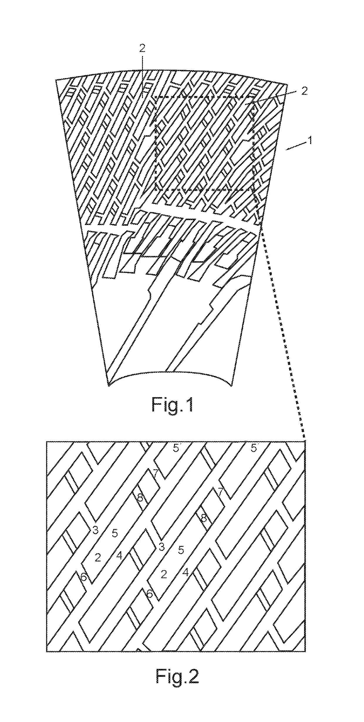
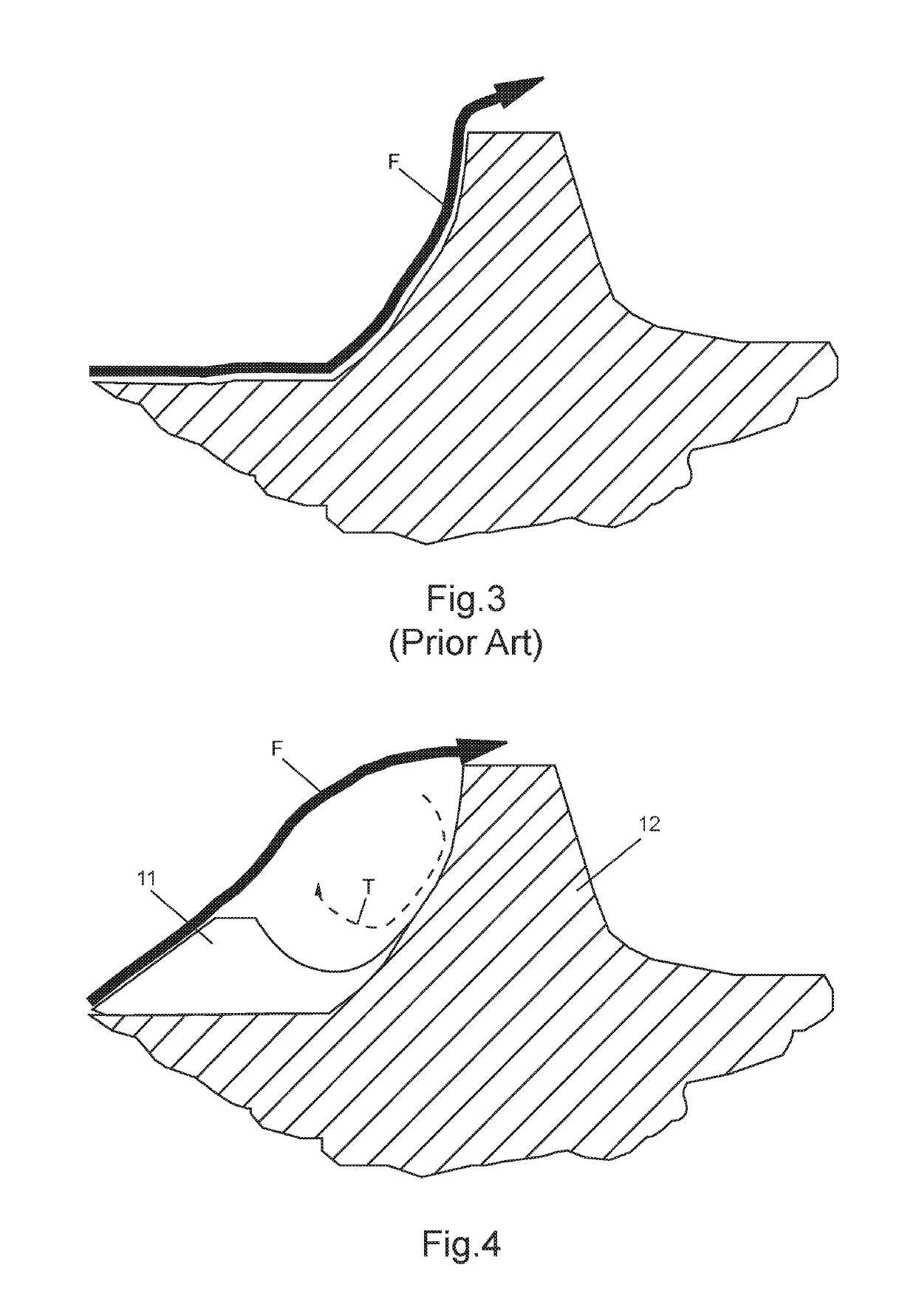
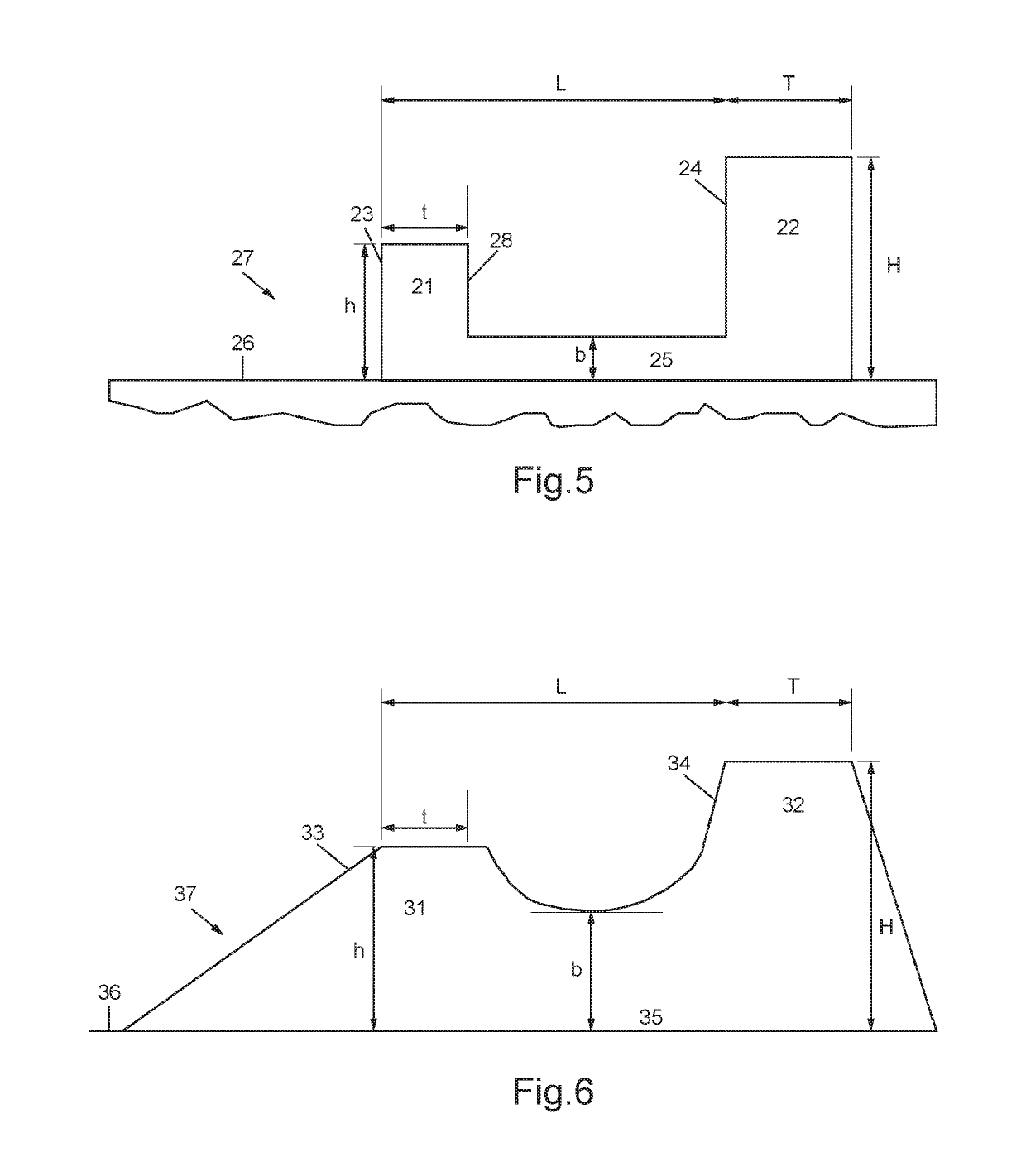
[0015]Below, the general shape and design of a refiner plate and a refiner plate segment according to the invention will first be explained with reference to FIG. 1 and FIG. 2; thereafter the advantages achieved over the prior art with such a refiner plate and refiner plate segment will be demonstrated with reference to FIG. 3 and FIG. 4, respectively; while specific ranges of dimensions for a first embodiment and a second embodiment of the invention will be presented with reference to FIG. 5 and FIG. 6, respectively.

[0016]FIG. 1 illustrates schematically a section of a refiner plate 1 according to the present invention. The refiner plate 1 comprises a number of segments 2, of which at least one segment 2 is provided with at least two bars, i.e. a first bar 3 and a second bar 4, as is best seen in the enlarged view of FIG. 2. The first bar 3 and the second bar 4 extend in a generally radial direction from the center of the refiner plate 1. As used herein, the term “generally radial ...


PUM

PropertyMeasurementUnit
heightaaaaaaaaaa
thicknessaaaaaaaaaa
centrifugal forcesaaaaaaaaaa

Abstract

The invention relates to a refiner plate segment in a refiner plate for mechanically refining of lignocellulosic material in a refiner, said refiner plate segment comprising at least a first, generally radially extending bar, a second, generally radially extending bar, a groove arranged and defined between said first, generally radially extending bar and said second, generally radially extending bar, and a main dam, which has a height H and is arranged in the groove, wherein a pre-dam is arranged in front of the main dam, said pre-dam has a height h which is less than the height H of the main dam.

Description

TECHNICAL FIELD[0001]The present invention relates generally to a refiner, such as a disc-type refiner, and particularly to a refiner plate to be used in such a refiner, and even more particularly to a dammed refiner plate segment, which is part of a refiner plate and which comprises a pre-dam arranged in front of a main dam.BACKGROUND OF THE INVENTION[0002]Lignocellulosic material, e.g., wood chips, saw dust and other fibrous material from wood or plant, is refined by mechanical refiners that separate fibers from the fiber network that forms the lignocellulosic material. A typical refiner for processing fibrous material is a disc-type refiner, wherein two refiner plates—which also are referred to as refiner discs—are positioned opposite to each and wherein at least one refiner plate rotates with respect to the other refiner plate. A rotating refiner plate or refiner disc may be referred to as a rotor, while a stationary refiner plate or refiner disc may be referred to as a stator. ...

Claims


Application Information

Patent Timeline
Patent Type & Authority Patents(United States)
IPC IPC(8): B02C7/00D21C3/22D21D1/30B02C7/12B02C7/02B02C7/04
CPCD21D1/306B02C7/00B02C7/02D21D1/303B02C7/12D21C3/222D21D1/30B02C7/04
Inventor LINDBLOM, THOMMY
Owner VALMET AB
Why Eureka
Try Eureka