Electromechanical low voltage switch

a low-voltage switch and electromechanical technology, applied in the direction of electric switches, electrical appliances, contacts, etc., can solve the problems of reducing the frequency of arcs very significantly, and prolonging the useful life of low-voltage switches, so as to improve the resistance capacity, reduce the mass of the support, and improve the effect of resistan

Inactive Publication Date: 2015-04-30
DODUCO GMBH CO DR EUGEN DURRWACHTER
View PDF4 Cites 0 Cited by
  • Summary
  • Abstract
  • Description
  • Claims
  • Application Information

AI Technical Summary

Benefits of technology

[0014]Preferably, the support is provided, at least in a partial region of the support that borders on the at least one contact piece, with a layer composed of an electrically well conductive material, which does not ignite in air under the effect of an arc. In this way, the risk that the light metal ignites under the effect of the arc, if the foot point of the arc were to move down from the contact piece attached to the support, can be prevented.
[0015]Well conductive metals such as copper, silver, iron, and alloys of these metals are particularly suitable as a material for the layer that does not ignite under the effect of an arc. Preferably, this layer is at least 0.1 mm thick. In the case of thinner layers, the risk that the arc penetrates the layer and ignites the light metal situated underneath it increases. It is practical if the layer is not thicker than 1 mm; a greater thickness leads to no significant improvement in the resistance capacity against the effect of an arc. Preferably, the thickness of the layer amounts to 0.4 mm to 0.6 mm.
[0016]Preferably, the support consists—with the exception of the layer of the material that does not ignite under the effect of an arc, which layer is provided on the support—in total of a light metal or of a light-metal alloy. This enables a particularly low mass of the support, thereby enabling a low or negligible tendency of the low voltage switch to bounce or making it easier to suppress bouncing. Compared to a conventional switch composed of copper, its mass can drop to less than half in this way, for example to ⅓ to ¼ of the mass of a conventional copper support having the same dimensions.
[0017]In order to enable the layer composed of the material that does not ignite under the effect of an arc to develop its desired effect, it must be provided on that side of the support to which the contact piece or—if two contact pieces are provided—the two contact pieces are attached. Such a layer does not need to be provided on the other sides of the support. Preferably, however, such a layer is also provided on that side of the support that faces away from the one contact piece or away from the multiple contact pieces of the support. This has the advantage that in the event of a change in the temperature of the support, different thermal expansion coefficients of the support material and of the material of the layer provided on the support do not lead to a curvature of the support.
[0018]It is practical if the layer composed of the material that does not ignite under the effect of an arc is provided on the entire surface of that side of the support to which the at least one contact piece is attached, and preferably also on the entire surface of that side of the support that faces away from the at least one contact piece. Then it is ensured, under all circumstances that the foot point of an arc, if it were to migrate down from one of the contact pieces, can, in any case, only migrate on the layer that consists of the material that does not ignite under the effect of an arc.
[0019]The electrically conductive support of the at least one contact piece frequently consists of a metal sheet and can be a part made by stamping or by stamping and bending. If a layer of the material that does not ignite under the effect of an arc is provided only on that side of the support on which the at least one contact piece is provided, which side will hereinafter be referred to as the front side of the support, and even if such a layer is provided on the back side of the support, which faces away from the at least one contact piece, but the support does not have a layer that does not ignite under the effect of an arc on all its surfaces, then corrosion, particularly contact erosion, can occur. In order to counter this, one could consider coating the support on all sides with the material that does not ignite under the effect of an arc. Coating of the support on all sides can take place by means of a wet-chemical coating process, namely in an electrolytic bath or in a bath that works with chemical reduction without externally applied current. In this manner, the support could be coated on all sides with a material that does not ignite under the effect of an arc, with electrolytic coating being preferred. However, it would be too elaborate to deposit the layer having a thickness of a few tenths of a millimeter, which is supposed to protect the support for the at least one electrical contact piece from the effect of an arc, entirely from an electrolytic bath or from a chemically reductive bath. For this reason, it is preferred to apply the layer that is supposed to withstand the effect of an arc to the front side of the support, and, if necessary, also to the back side of the support, facing away from the front side, in a thickness of several tenths of a millimeter, by means of roll cladding, and to protect the surfaces not covered by the roll-cladded layer, particularly the lateral cut surfaces of the support, in that a material that does not ignite under the effect of an arc is deposited by a wet-chemical process, particularly by electrodeposition. It is practical to use the same material as for the roll cladding, particularly copper, for this purpose, in a layer thickness of several μm. Preferably, such a protective layer is applied to the support on all sides, if necessary also to the layer that has already been applied by means of roll cladding, composed of the material that does not ignite under the effect of an arc. Only afterward the at least one contact piece is attached to the support, using a usual method, for example by means of welding, brazing, or riveting.

Problems solved by technology

1) Compared to a support composed of copper, which is usual in the state of the art, a support according to the invention, having the same dimensions as in the state of the art, has a lower mass than a support composed of copper. As a result, the tendency to bounce is reduced or entirely prevented. As a further consequence, the frequency of the occurrence of arcs decreases very significantly. The occurrence of fewer arcs leads to a longer useful lifetime of the low voltage switch.
2) The closing and opening movements that otherwise occur during bouncing and rapidly follow one another can generate interference signals that lead to problems in a downstream electrical or electronic circuit. Such problems can be avoided by means of the avoidance of bouncing events according to the invention. Filters and similar circuits for preventing or suppressing interference signals can become superfluous, according to the invention.

Method used


Image

  • Electromechanical low voltage switch
  • Electromechanical low voltage switch

Examples


Embodiment Construction

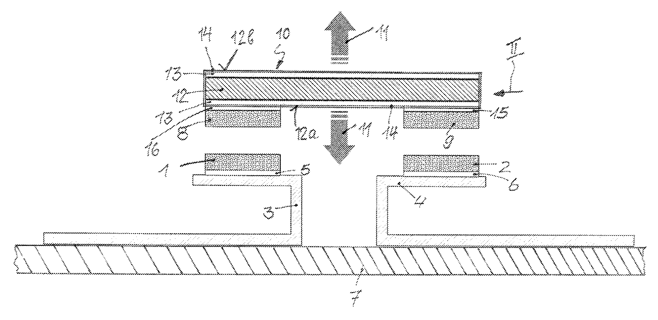
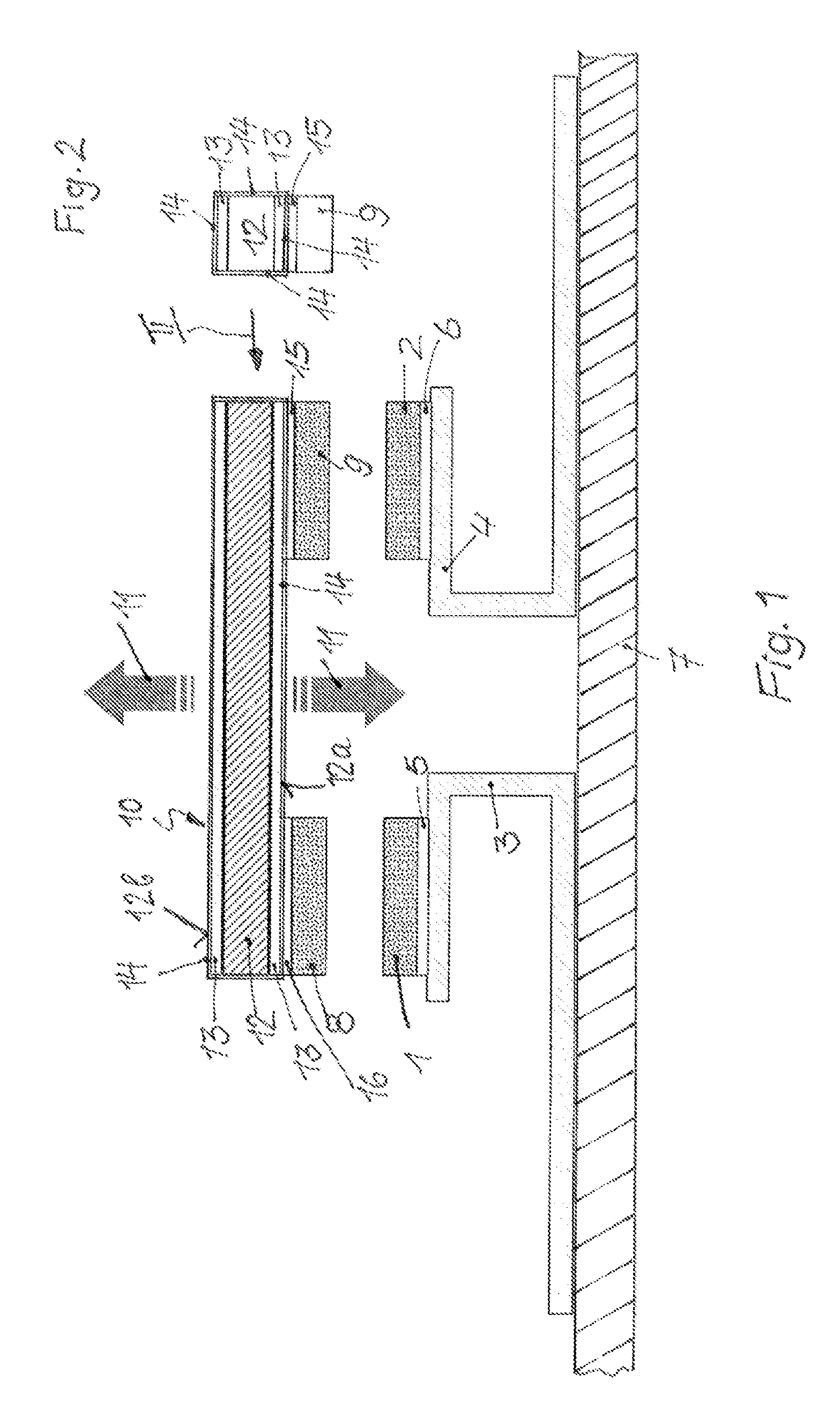
[0033]The low voltage switch has two fixed contacts 1 and 2, which are attached to two conductor lines 3 and 4, for example by brazing, which lines in turn are mounted on an insulating support plate 7. A brazing solder layer 5 or 6, respectively, is provided between each of the two fixed contacts 1 and 2 and the conductor lines 3 and 4, respectively.

[0034]Two movable contact pieces 8 and 9 lie opposite the two fixed contacts 1 and 2, which pieces are attached to a switching element 10 configured as a contact bridge, which switching element can be moved forward and back by means of an actuator, represented symbolically by the two arrows 11, in order to either bring the contact pieces 8 and 9 into contact with the fixed contacts 1 and 2 that lie opposite them, thereby creating a conductive connection between the two conductor lines 3 and 4, or in order to lift the contact pieces 8 and 9 off from the fixed contacts 1 and 2, thereby interrupting the conductive connection between the two...


PUM


Abstract

An electromechanical low voltage switch has a movable switching element that has an electrically conductive support and at least one electrical contact piece attached to this support. The support consists, at least in part, of a metal or of an alloy, the density of which lies below 5 g/cm3.

Description

CROSS-REFERENCE TO RELATED APPLICATIONS[0001]This continuation application claims priority to PCT / EP2013 / 063427 filed on Jun. 26, 2013 which has published as WO 2014 / 005908 A1 and also the German application No. 10 2012 106 053.3, filed Jul. 5, 2012, the contents of which are fully incorporated herein with these references.DESCRIPTION[0002]1. Field of the Invention[0003]The invention relates to an electromechanical low voltage switch in accordance with the preamble of independent claim, having a movable switching element that has an electrically conductive support and at least one electrical contact piece attached to this support.[0004]2. Background of the Invention[0005]On closing the switch the movable contact piece impacts a fixed contact. In this connection, bouncing of the two contacts can occur. Bouncing is a mechanically triggered interference effect. For a short time, in the millisecond range, multiple closing and opening of the switch occurs. More rarely, bouncing can also ...

Claims


Application Information

Patent Timeline
Patent Type & Authority Applications(United States)
IPC IPC(8): H01H1/50
CPCH01H1/50H01H1/021H01H1/0231H01H11/041H01H1/20H01H2011/046H01H3/60H01H11/045
Inventor MOOG, DIRK
Owner DODUCO GMBH CO DR EUGEN DURRWACHTER
Why Eureka
Try Eureka