
Method for obtaining pure copper

a technology of pure copper and copper blocks, applied in the field of obtaining pure copper, can solve the problems of affecting the corrosion of the copper block, and the impact of solidification of copper, so as to increase the useful life of the splash protection device

Active Publication Date: 2006-04-27
XSTRATA TECH PTY LTD
View PDF8 Cites 0 Cited by
  • Summary
  • Abstract
  • Description
  • Claims
  • Application Information

AI Technical Summary

Benefits of technology

[0008] It is an object of the present invention to provide a method having the characteristics described above, which guarantees an increased useful lifetime of the splash protection device.
[0011] According to a preferred embodiment of the invention, the boiling water pressure is more than 20 bar, corresponding to a boiling temperature of about 212° C. Under some circumstances, however, boiling water pressures of more than 5 bar or more than 10 bar, respectively, are already sufficient to guarantee a sufficiently long useful lifetime. It is practical if the water is already close to the boiling point as it enters into the splash protection device. Having the water close to boiling has the additional advantage that a crack occurs in the splash protection device, or if another kind of leak occurs, no cold water gets into the copper melt, because the boiling water evaporates immediately upon entering the melting furnace atmosphere.
[0012] In another embodiment, the boiling water is connected to a cooling water circuit of the waste heat boiler in the inflow and outflow. In this way, circulation pumps of a boiler system that includes the waste heat boiler, which are present, can be advantageously used to transport the water that flows through the waste heat boiler. Furthermore, the steam that is generated as the water flows through the splash protection device can be passed to a heat recovery device of the boiler system.

Problems solved by technology

However, although melting of the copper is effectively prevented by means of the cold cooling water, erosion corrosion takes place at the copper block, because of sulfur contained in the copper melt.
Another problem is that if a crack caused by corrosion phenomena occurs in the splash block, cold cooling water penetrates into the copper melt.
The water evaporates explosively there and thereby results in a massive impact of solidifying copper splashed out of the melt against the waste heat boiler.

Method used


Image

  • Method for obtaining pure copper
  • Method for obtaining pure copper
  • Method for obtaining pure copper

Examples


Embodiment Construction

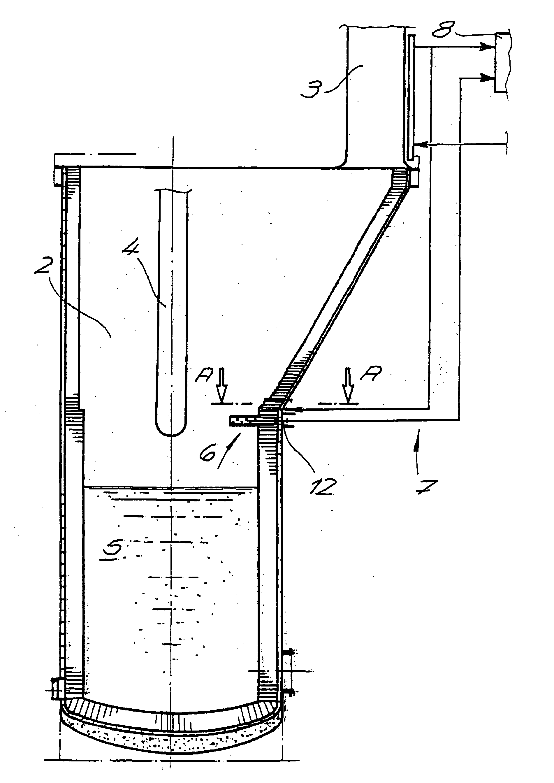
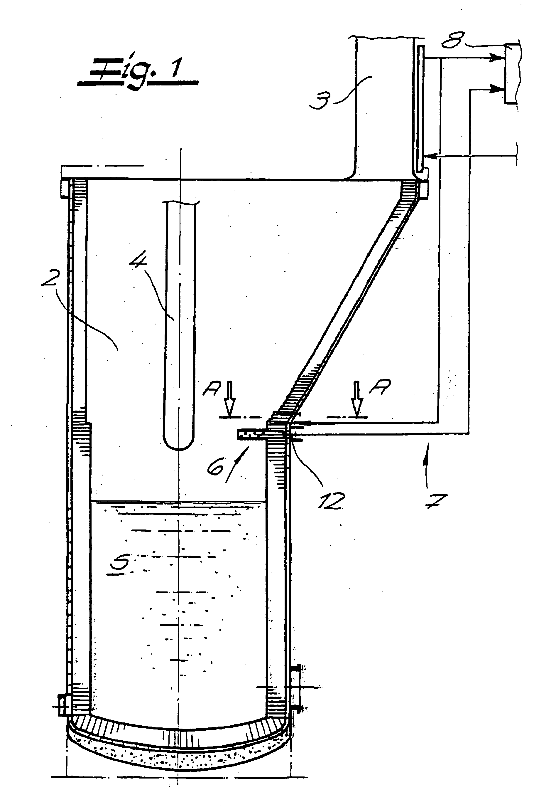
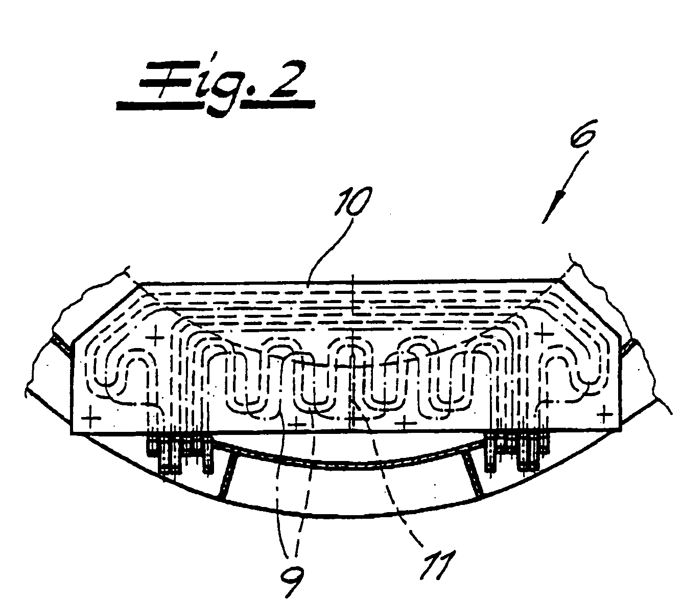
[0018]FIG. 1 shows a detail of a system for obtaining pure copper. The system has a melting furnace 2 lined with refractory material. Melting furnace 2 has a waste heat boiler 3 set onto it at a lateral offset. Oxygen, or even air, is blown onto a copper melt 5 that is located in the melting furnace, using a lance 4, in order to oxidize contaminants contained in melt 5 and thereby remove them from melt 5. While the solid oxidation products generally accumulate at the surface of the copper melt 5 as slag, the gaseous oxidation products are transported away from the melt furnace 2 by way of waste heat boiler 3. The temperature of copper melt 5 is approximately 1,300° C., whereas the waste gases that are formed in waste heat boiler 3 are cooled off to approximately 700° C.

[0019] Waste heat boiler 3 is followed by another cooling device in the form of a quench, not shown, which cools the waste gases down to approximately 350° C. Above copper melt 5, on the inside wall of melting furnac...


PUM

PropertyMeasurementUnit
pressureaaaaaaaaaa
pressureaaaaaaaaaa
pressureaaaaaaaaaa

Abstract

A method for obtaining pure copper is provided wherein oxygen is blown onto a copper melt, in a melting furnace lined with refractory material, having a waste heat boiler set onto it, in order to oxidize contaminants contained in the melt and thereby remove them from the melt, and wherein a splash protection device through which water flows is provided above the copper melt, on the inside wall of the melting furnace, which prevents copper that splashes out of the copper melt from penetrating into the waste heat boiler. Boiling water is used for cooling the splash protection device, which water is under a pressure of more than 5 bar and is evaporated, at least in part, as it flows through the splash protection device.

Description

CROSS REFERENCE TO RELATED APPLICATIONS [0001] Applicants claim priority under 35 U.S.C. §119 of German Application No. 10 2004 049 234.4 filed Oct. 9, 2004. BACKGROUND OF THE INVENTION [0002] 1. Field of the Invention [0003] The present invention relates to a method for obtaining pure copper. More specifically, in the method, oxygen is blown onto a copper melt, in a melting furnace lined with refractory material, having a waste heat boiler set onto it, in order to oxidize contaminants contained in the melt and thereby remove them from the melt. In addition, a splash protection device through which water flows is provided above the copper melt, on the inside wall of the melting furnace. The splash protection device prevents copper that splashes out of the copper melt from penetrating into the waste heat boiler. [0004] 2. The Prior Art [0005] Methods having the characteristics described above are known in practice. The splash protection device, which is frequently also referred to as...

Claims


Application Information

Patent Timeline
Patent Type & Authority Applications(United States)
IPC IPC(8): C22B15/14
CPCC22B15/0045C22B15/006F27B3/225F27D9/00
Inventor KASCHUB, HARTWIGBLANKE, MARTIN
Owner XSTRATA TECH PTY LTD
Learn More