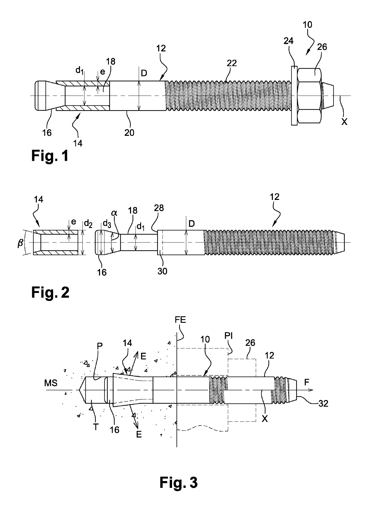
Expanding wall anchor and use for fixing a component to a support material

a technology for supporting materials and expansion walls, which is applied in the direction of fastening means, dowels, mechanical equipment, etc., can solve the problems of product performance decline, product performance drop, and product failure to meet the earlier type testing certification conditions, etc., to reduce the holding performance of wall anchors, improve operation, and improve the effect of performan

Active Publication Date: 2019-08-20
ILLINOIS TOOL WORKS INC
View PDF31 Cites 3 Cited by
  • Summary
  • Abstract
  • Description
  • Claims
  • Application Information

AI Technical Summary

Benefits of technology

[0019]A large angle α generates significant stress at the contact between the sleeve and the expansion cone of the body. This stress, if excessively high, has the effect of causing the sleeve to seize on the body, destroying the contact surface, which is detrimental to the overall operation of the wall anchor under such conditions. Sometimes the person skilled in the art uses an antifriction coating at this point of contact, in order to push back the limits of seizure described above. However, this coating has the disadvantage of reducing the holding performance of the wall anchor under the conditions described above. The applicant company, seeking to obtain superior performance despite the new seismic conditions, has raised the value of this angle α to at least 27°, which goes against the technical preconceptions in this art. Astonishingly, recourse to these high angle α values has made it possible to improve the operation and hold fast ability of the wall anchors. Increasing the value of the angle α without seizure has in fact between made easier by the increase in the thickness e of the sleeve which allows this sleeve to withstand more severe operating conditions and makes it possible to push back the permissible limits at the sleeve / expansion cone contact region. The combination of these parameters has allowed the applicant company to produce wall anchors that function perfectly under seismic loading in cracked concrete while at the same time improving their ultimate strength, and as a result, their maximum safe working load.

Problems solved by technology

This results in increasingly strict product testing conditions.
The known products which were able to meet the earlier type testing certification conditions generally experience a drop in their performance, or even sometimes are no longer able to function at all under seismic loadings.
These changes to the type testing certification conditions, particularly the increase in the width of the cracks in the support material accepting this type of wall anchor during the certification testing, mean that the sleeve has greater difficulty holding fast in the support material, or suitably holding the body of the wall anchor when the latter experiences seismic loadings.

Method used


Image

  • Expanding wall anchor and use for fixing a component to a support material

Examples


example

[0057]The description that follows contains a comparative example to illustrate the foregoing.

[0058]We have compared a product according to the invention (product A) that meets all of the requirements stipulated for cracked concrete and seismic loadings against a product of the prior art that meets only the requirements stipulated for cracked concrete without seismic loadings (product B) and against a third product designed exclusively for non-cracked concrete (product C). The three wall anchors compared have the same nominal diameter, in this instance 12 mm (M12), and were set at identical anchoring depths into concretes of identical strengths. The various components of these wall anchors are made of comparable steels commonly used by those skilled in the art. The only appreciable differences are their ratio e / d1 and their angle α as defined above. The reference wall anchor is the wall anchor according to the invention (product A) which works under all the conditions and for which ...


PUM


Abstract

Expanding wall anchor, comprising (i) a threaded longitudinal body formed as a single piece with an expansion cone at one of its ends, this cone being connected to the rest of the body by a cylindrical portion of diameter d1 smaller than the nominal diameter D of the body, and (ii) an expanding sleeve of thickness e mounted around the said cylindrical portion of the body and through which the expansion cone is intended to be moved in order to deform the sleeve and anchor the wall anchor in a hole in a support material, characterized in that the ratio d1 / D is greater than or equal to 60% and the ratio e / d1 is greater than or equal to 22%.

Description

RELATED APPLICATIONS[0001]The present application is a National Phase of International Application Number PCT / US2014 / 052199, filed Aug. 21, 2014, and claims priority to French Application Number 1361072, filed Nov. 13, 2013.TECHNICAL FIELD[0002]The invention relates to an expanding wall anchor and its use for fixing a component to a support material, particularly a support material liable to be subjected to seismic loadings.PRIOR ART[0003]Typically, an expanding wall anchor comprises i) a threaded longitudinal body formed as a single piece with an expansion cone at one of its ends, this cone being connected to the rest of the body by a cylindrical portion of diameter smaller than the nominal diameter of the body, and ii) an expanding sleeve mounted around the said cylindrical portion of the body and through which the expansion cone is intended to be moved in order to deform the sleeve and anchor the wall anchor in a hole in a support material.[0004]Documents US-A1-2010 / 0104393 and W...

Claims


Application Information

Patent Timeline
Patent Type & Authority Patents(United States)
IPC IPC(8): F16B13/06
CPCF16B13/065
Inventor POURTIER, FABRICE
Owner ILLINOIS TOOL WORKS INC
Why Eureka
Try Eureka