
Refrigeration cycle apparatus

a technology of refrigerating cycle and apparatus, which is applied in the direction of lighting and heating apparatus, positive displacement liquid engine, heating type, etc., can solve the problems of low-gwp refrigerants that are difficult to apply, performance deterioration, and the inability to secure withstanding pressure, so as to reduce the gwp of mixed refrigerants

Active Publication Date: 2019-08-27
MITSUBISHI ELECTRIC CORP
View PDF19 Cites 2 Cited by
  • Summary
  • Abstract
  • Description
  • Claims
  • Application Information

AI Technical Summary

Benefits of technology

The present invention relates to a refrigeration cycle apparatus that uses a mixed refrigerant containing less than 50% of 1,1,2-trifluoroethylene. This reduces the amount of 1,1,2-trifluoroethylene in the refrigerant circuit, which prevents disproportionation reaction. The refrigeration cycle apparatus also uses a refrigerating machine oil that is soluble in diverfluoromethane, which prevents an increase in the proportion of 1,1,2-trifluoroethylene during operation. The mixed refrigerant has a mixing ratio of difluoromethane to 1,2,2-trifluoroetylene of 0.7 or more, but not more than two times the mixing ratio of 1,2,2-trifluoroetylene. This results in a pseudo-azeotropic state, preventing separation between 1,1,2-trifluoroethylene and difluoromethane and further preventing disproportionation reaction. Additionally, the refrigeration cycle apparatus uses 2,3,3,3-tetrafluoropropenee to reduce the global warming potential (GWP) of the mixed refrigerant.

Problems solved by technology

These low-GWP refrigerants are difficult to apply to typical air-conditioning apparatus because of the following problems.R744: There is a problem in securing withstanding pressure because of very high operating pressure.
Also, because critical temperature is as low as 31 degrees C., there is a problem of how to secure performance in application to air-conditioning apparatus.R717: Because of high toxicity, there is a problem in ensuring safety.R290: Because of high flammability, there is a problem in ensuring safety.HFO-1234yf / HFO-1234ze: Because a volume flow rate increases at low operating pressure, there is a problem of performance deterioration due to increases in pressure loss.

Method used


Image

  • Refrigeration cycle apparatus
  • Refrigeration cycle apparatus
  • Refrigeration cycle apparatus

Examples


embodiment

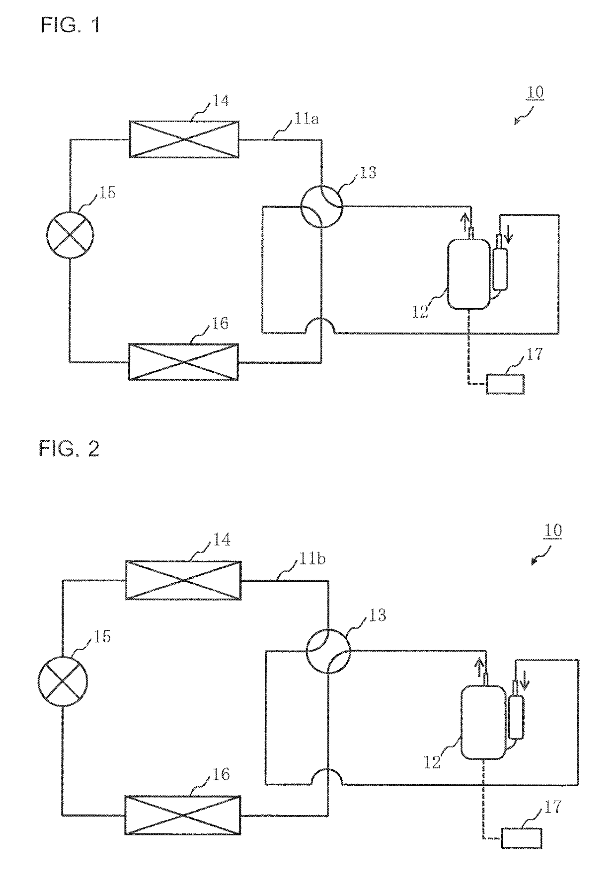
[0030]FIGS. 1 and 2 are circuit diagrams of a refrigeration cycle apparatus 10 according to an embodiment of the present invention, where FIG. 1 shows a refrigerant circuit 11a during cooling and FIG. 2 shows a refrigerant circuit 11b during heating.

[0031]According to the present embodiment, the refrigeration cycle apparatus 10 is an air-conditioning apparatus. Note that the present embodiment is also applicable when the refrigeration cycle apparatus 10 is other than an air-conditioning apparatus (e.g., a heat pump cycle apparatus).

[0032]In FIGS. 1 and 2, the refrigeration cycle apparatus 10 includes refrigerant circuits 11a and 11b through which refrigerant circulates.

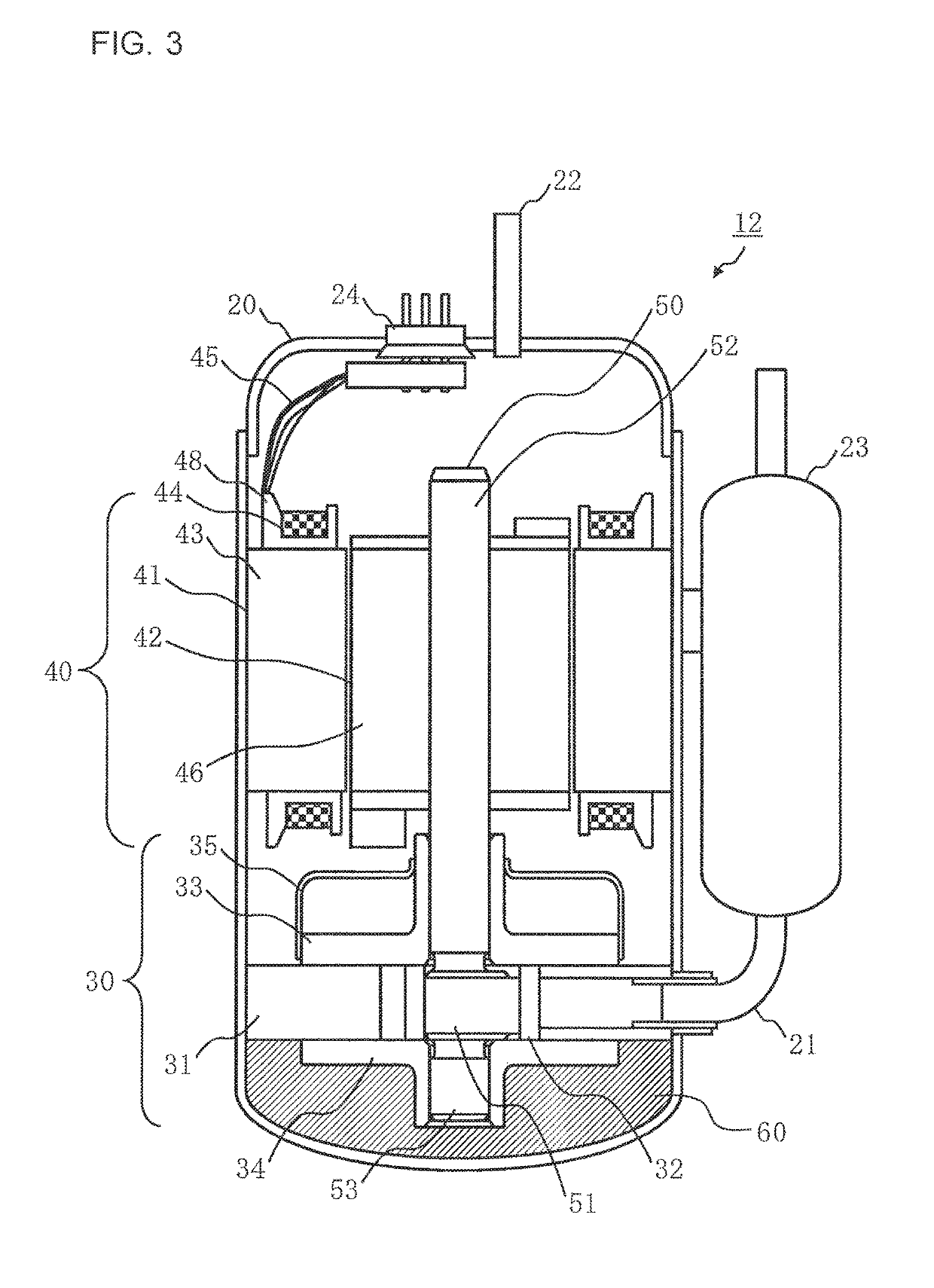
[0033]The refrigerant circuits 11a and 11b are connected with a compressor 12 which is a high pressure shell compressor (compressor adapted to discharge the refrigerant compressed by a compression element into an airtight container), a four-way valve 13, an outdoor heat exchanger 14, an expansion valve 15, and an indo...


PUM

PropertyMeasurementUnit
GWPaaaaaaaaaa
GWPaaaaaaaaaa
weight ratioaaaaaaaaaa

Abstract

A refrigeration cycle apparatus includes refrigerant circuits in which a high pressure shell compressor, an outdoor heat exchanger, an expansion valve, and an indoor heat exchanger are connected; a mixed refrigerant made up of a mixture of 1,1,2-trifluoroethylene, difluoromethane, and 2,3,3,3-tetrafluoropropene and configured to circulate through the refrigerant circuits, the mixed refrigerant containing less than 50 wt % of 1,2,2-trifluoroetylene and a mixing ratio of difluoromethane being between 0.7 times and two times (both inclusive) that of 1,2,2-trifluoroetylene in terms of weight ratio, in a state before the mixed refrigerant is enclosed in the refrigerant circuits; and a refrigerating machine oil enclosed in the refrigerant circuits and prepared such that difluoromethane is least soluble in the refrigerating machine oil.

Description

CROSS REFERENCE TO RELATED APPLICATION[0001]This application is a U.S. national stage application of PCT / JP2014 / 077527 filed on Oct. 16, 2014, the contents of which are incorporated herein by reference.TECHNICAL FIELD[0002]The present invention relates to a refrigeration cycle apparatus.BACKGROUND ART[0003]In recent years, there has been demand to reduce greenhouse gasses from a perspective of preventing global warming. Regarding refrigerants used for refrigeration cycle apparatus such as air-conditioning apparatus, those with a lower global warming potential (GWP) are being considered. The GWP of R410A widely used for air-conditioning apparatus at present is as high as 2088. Difluoromethane (R32) that has begun to be introduced recently has a considerably high GWP value of 675.[0004]Examples of refrigerant with a low GWP include carbon dioxide (R744: GWP=1), ammonia (R717: GWP=0), propane (R290: GWP=6), 2,3,3,3-tetrafluoropropenee (HFO-1234yf: GWP=4), and 1,3,3,3-tetrafluoropropene...

Claims


Application Information

Patent Timeline
Patent Type & Authority Patents(United States)
IPC IPC(8): C09K5/04F24F1/32F25B1/00F24F1/16F25B9/00F25B31/00C10M171/00F04B39/06
CPCC09K5/045C10M171/008C10M2207/2835C10M2209/043C10M2209/1033C10N2040/30C09K5/04C09K2205/126C09K2205/22F25B1/00C10M105/38C10M107/24C10M107/34F25B9/006F04B39/062F24F1/16F24F1/32F25B31/004
Inventor MAEYAMA, HIDEAKI
Owner MITSUBISHI ELECTRIC CORP
Learn More