System and method for use of flexible anti-reflux ureteral stent

a ureteral stent and flexible technology, applied in the field of stent systems and methods, can solve the problems of patients suffering from bleeding, numerous side effects of existing ureteral stents, and various other undesirable side effects, and achieve the effects of reducing patient irritation, preventing migration, and enhancing patient comfor

Active Publication Date: 2019-09-03
THE GENERAL HOSPITAL CORP
View PDF30 Cites 0 Cited by
  • Summary
  • Abstract
  • Description
  • Claims
  • Application Information

AI Technical Summary

Benefits of technology

[0008]The present invention overcomes the aforementioned drawbacks by providing a stent including one or more flexible elements which may be achieved by materials having different hardness properties or by a single material with different types of reinforcement and / or thicknesses, and whereby the stent incorporates a self-retaining securement mechanism to assist in preventing migration. The self-retaining securement mechanism is substantially more rigid than a majority of the rest of the stent and the softer material enhances patient comfort and minimizes patient irritation. The stent may further incorporate a valve therein to address reflux problems.
[0010]In a different configuration, a stent includes an elongate conduit defined by a renal portion and a bladder portion. A valve is disposed within the conduit, and between about 75% to about 99% of the conduit is characterized by a hardness of less than about 80 Shore A. The valve facilitates fluid flow only in one direction through the conduit.

Problems solved by technology

There are numerous problems and side effects associated with existing ureteral stents, however.
One such problem is migration of the stent after insertion such that the stent does not remain in the specified location over the duration that the stent is disposed within the patient.
Stents utilizing a double J design are more successful in retaining the ureteral stent in the desired location in the patient, but cause various other undesirable side effects due to the lower coil being disposed adjacent to and aggravating the patient's bladder.
For example, the lower coil frequently causes the patient to suffer from bleeding, urges to pass urine frequently, and burning while passing urine due to the coil scratching the bladder.
Existing ureteral stents have insufficient mechanisms to control reflux that also allow for urine flow to pass from the patient.
Reflux may cause pain (sometimes severe) in some patients and may lead to serious health conditions including urinary tract infections and even renal failure in extreme cases.
However, significant drawbacks exist with this stent design.
For example, the stent includes a significant portion of rigid material that irritates the patient's urinary tract and results in patient discomfort.
Further, this stent design does not include a mechanism to control reflux.

Method used


Image

  • System and method for use of flexible anti-reflux ureteral stent
  • System and method for use of flexible anti-reflux ureteral stent
  • System and method for use of flexible anti-reflux ureteral stent

Examples


Embodiment Construction

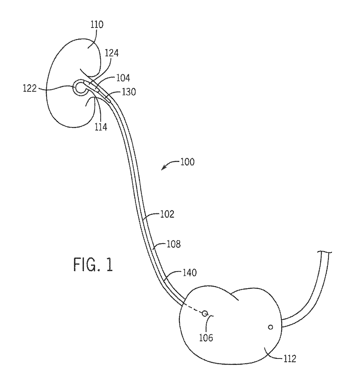
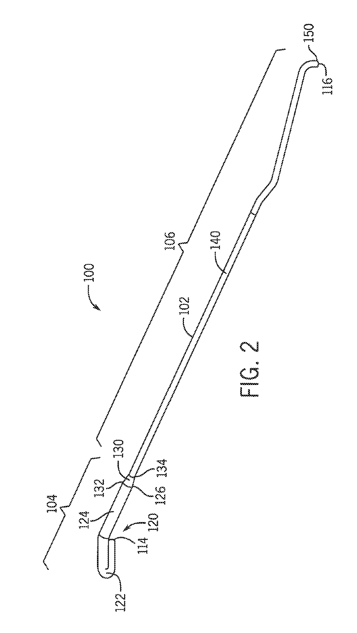
[0027]As best seen generally in FIGS. 1-14, a stent 100 includes an elongate conduit 102 having a renal portion 104 and a bladder portion 106. The elongate conduit 102 defines at least one lumen, which allows fluid communication therethrough. The stent 100 is designed to be placed or otherwise positioned in a passageway of a patient (e.g., urinary tract), and in particular, into a patient's ureter 108. The renal portion 104 of the stent 100 is designed to be positioned proximate the patient's kidney 110 and the bladder portion 106 is designed to be positioned proximate the patient's bladder 112. The stent 100 provides a passageway from the kidney 110 to the bladder 112 through the ureter 108 to allow urine to flow unimpeded and exit from the patient through the urethra (not shown).

[0028]In one embodiment, the stent 100 is defined by at least two separate materials having a different hardness parameter as discussed herein. In a different embodiment, the stent 100 is defined by the sa...


PUM


Abstract

The multi-material stent includes a renal portion and a bladder portion with respective, different hardness. A valve is disposed within the stent to guide liquid from the renal portion of the stent to the bladder portion of the stent. The present invention relates towards systems and method for stents. More particularly, the invention relates to a stent designed to increase patient comfort by minimizing irritation and reflux through the use of a stent that incorporates one or more flexible elements, which may involve materials with varying degrees of hardness, and a valve disposed therein.

Description

CROSS-REFERENCE TO RELATED APPLICATIONS[0001]The present application represents the national stage entry of PCT International Application No. PCT / US2014 / 025321 filed Mar. 13, 2014, which is based on, and claims priority to U.S. Provisional Application Ser. No. 61 / 782,272, filed Mar. 14, 2013, both of which are incorporated herein by reference in their entirety for all purposes.STATEMENT REGARDING FEDERALLY SPONSORED RESEARCH[0002]N / ABACKGROUND OF THE INVENTION[0003]The present invention relates towards systems and method for stents. More particularly, the invention relates to a stent designed to increase patient comfort by minimizing irritation and reflux through the use of a stent that incorporates one or more flexible elements, which may involve materials with varying degrees of hardness, and a valve disposed therein.[0004]Stents are thin, hollow tubes inserted into a conduit in a patient to assist in opening a passageway that has been obstructed, or to assist in maintaining a pas...

Claims


Application Information

Patent Timeline
Patent Type & Authority Patents(United States)
IPC IPC(8): A61F2/04A61M27/00
CPCA61F2/04A61M27/008A61F2/042A61F2002/047A61F2002/048A61F2230/0069
Inventor EISNER, BRIAN H.MILLER, SCOTT
Owner THE GENERAL HOSPITAL CORP
Why Eureka
Try Eureka