Insulating body for a plug connector

a technology of insulation body and plug connector, which is applied in the direction of connection, electrical apparatus, coupling device connection, etc., can solve the problems of inability to reliably molded in the injection molding process, limited space available for such guide members,

Active Publication Date: 2019-09-03
HARTING ELECTRIC GMBH & CO KG
View PDF11 Cites 3 Cited by
  • Summary
  • Abstract
  • Description
  • Claims
  • Application Information

AI Technical Summary

Benefits of technology

[0004]Embodiments of the present invention provide an insulating body of the type initially mentioned to the effect that the installation safety for the contacts is increased with little effort.
[0005]According to embodiments of the invention, provision is made in an insulating body of the type initially mentioned that at least one peripheral edge of the seat has a guide web provided thereon which is elastic in the radial direction of the seat and which has a wall thickness that is greater at the free end than in the region of the connection to the seat. Embodiments of the invention are based on the finding that a special configuration of the guide webs allows them to be formed with a comparatively filigree design, without the need to use any expensive special plastics in producing the insulating body. According to aspects of the invention, it has been found that a guide web thickened at its free end can be reliably molded in an injection molding process, even if the wall thickness of the guide web is on the order of 0.4 to 0.8 mm. A guide web of such thinness can be provided even in confined spaces. The guide web ensures that the contact will automatically correctly enter the open seat during insertion. This prevents any incorrect installation.
[0008]In some instances, it is provided that the free ends of the two guide webs are opposite each other at a distance which is on the order of 10% to 40% of the diameter of the seat. This makes the seat provided for the contact appear to be almost closed when the latter is inserted into the insulating body, thus reducing the risk of misalignment.

Problems solved by technology

It is a drawback, however, that it may possibly occur that a contact is pushed in slightly obliquely when it is inserted, so that it is then seated at an angle, rather than being placed in the desired position concentrically within the seat.
However, since a very large number of contacts are possibly arranged closely next to each other in such an insulating body, the space available for such guide members is very limited.
If guide members are used which have a very filigree or delicate design due to the problems of space, there is the problem that they cannot be reliably molded in the injection molding process used for manufacturing the insulating body; a certain minimum wall thickness is required for reliable molding, or very expensive special plastics have to be used for very small wall thicknesses, which can be reliably processed even under these circumstances.

Method used


Image

  • Insulating body for a plug connector
  • Insulating body for a plug connector
  • Insulating body for a plug connector

Examples


Embodiment Construction

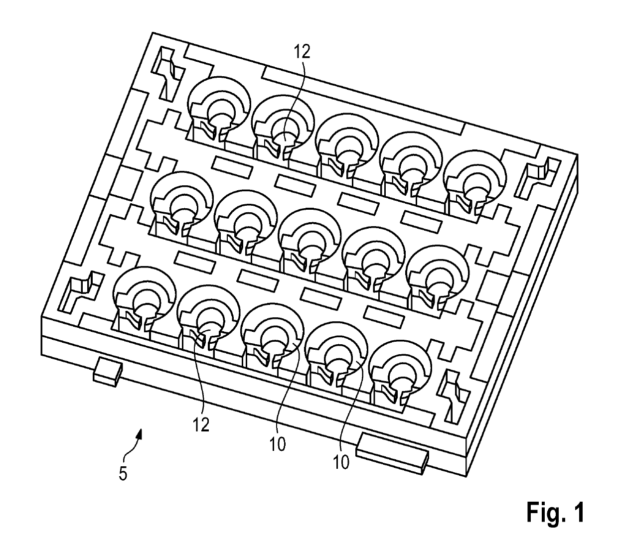
[0019]FIG. 1 shows an insulating body 5 for a plug connector, which is provided with a total of 15 seats 10 for contacts (not illustrated here).

[0020]The insulating body 5 is made from an injection molded plastic material.

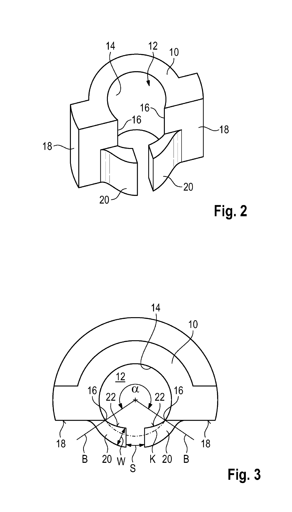
[0021]FIGS. 2 and 3 show one of the seats 10 in detail. Each seat 10 surrounds a receiving space 12 into which a contact having a circular cross-section can be inserted. As can be seen by the boundary lines B drawn in FIG. 3, the seat 10 encloses the receiving space 12 over an angular range a that is noticeably greater than 180 degrees but amounts to less than 300 degrees. In the exemplary embodiment shown, the angle α is in the range of from 210 degrees to 240 degrees.

[0022]The inner surface 14 of the seat 10 has an (at least almost) constant radius of curvature, the radius of curvature substantially corresponding to the radius of the contact to be received in the receiving space 12. In fact, the dimensions of the receiving space 12 are slightly smaller than the c...


PUM


Abstract

An insulating body for a plug connector is provided, having at least one seat for a contact, the seat being open in the peripheral direction and surrounding a receiving space for the contact over an angular range which is greater than 180 degrees and smaller than 300 degrees, and wherein at least one peripheral edge of the seat has a guide web provided thereon which is elastic in the radial direction of the seat and which has a wall thickness that is greater at the free end than in the region of the connection to the seat.

Description

BACKGROUNDTechnical Field[0001]This disclosure relates to an insulating body for a plug connector, including at least one seat for a contact, the seat being open in the peripheral direction and surrounding a receiving space for the contact over an angular range which is greater than 180 degrees and smaller than 300 degrees.Description of the Related Art[0002]Such a seat of the aforementioned type that is open on one side offers the advantage of being elastic so that a contact can be inserted into it, which is then reliably retained there. It is a drawback, however, that it may possibly occur that a contact is pushed in slightly obliquely when it is inserted, so that it is then seated at an angle, rather than being placed in the desired position concentrically within the seat.[0003]It would be basically conceivable to provide additional guide members in the region of the seat, which can serve to prevent that the contact can be inserted in the insulating body with an incorrect orienta...

Claims


Application Information

Patent Timeline
Patent Type & Authority Patents(United States)
IPC IPC(8): H01R13/426H01R13/436
CPCH01R13/426H01R13/436
Inventor WANG, XIAFUKEIL, MATTHIAS
Owner HARTING ELECTRIC GMBH & CO KG
Why Eureka
Try Eureka