High efficiency distillation head and methods of use

a high-efficiency, distillation head technology, applied in the direction of distillation in boilers/stills, fractional distillation, separation processes, etc., can solve the problems of slow throughput and decrease the efficiency of the distillation head, and achieve the effects of increasing thermal and infrared heat retention, high efficiency, and greater temperature differential

Active Publication Date: 2019-09-10
LAB SOC LLC
View PDF53 Cites 7 Cited by
  • Summary
  • Abstract
  • Description
  • Claims
  • Application Information

AI Technical Summary

Benefits of technology

[0006]The current invention provides a high efficiency distillation head and methods of use. The distillation head may be used for efficient fractional distillation of high boiling point compounds, and includes a lower insulated chamber surrounding a fractionating column and an upper insulated chamber surrounding a condenser. An exit path having a cross sectional area that is equal to or greater than the cross sectional area of the fractionating column is located on the distillation head at or below the top of the fractionating column. The lower insulated chamber can also feature a vacuum chamber having silvering (mirroring) inside of the vacuum chamber (i.e., vacuum jacket) to increase thermal and infrared heat retention, while leaving the upper insulated chamber un-silvered (not mirrored), which allows for a greater temperature differential and greater condensation efficiency of fractionated vapors.
[0007]A distillation head according to selected embodiments may be used in conjunction with a vacuum system and heated boiling flask (with product inside) to fractionate and separate high boiling point compounds. The device can be used, for example, to separate cannabinoids, from other constituents found in cannabis oils or constituents from other herbs. The fractionating column is engineered to promote separation while keeping the fractionating column short enough to keep the energy required below a certain threshold and maintaining the compound in its vapor phase. In one embodiment, the threshold is 175° C. In one embodiment, the threshold is 180° C. In another embodiment, the threshold is 190° C. In one embodiment, the threshold is 200° C. In another embodiment, the threshold is between about 175° C. and about 210° C. This works by employing two insulated chambers, a lower insulated chamber and an upper insulated chamber. The lower insulated chamber is hotter because it is heated by the vapor in the fractionating column and the upper insulated chamber is cooler to promote condensation of vapors exiting the fractionating column. A feature of this design compared to others is that the fractionating column exits to a larger condenser thereby resulting in much higher condensation (flow) rates in the head. Another feature of this design compared to others is that both the lower and upper insulation chambers feature vacuum chambers (i.e., vacuum jackets), with the lower insulated vacuum chamber having the option of silvering (mirroring). Utilizing this dual-chamber design, the distillation head can maintain a temperature differential between the lower vacuum chamber (fractionating) and the upper vacuum chamber (condensing) without the use of coolants, heaters, or chillers. Essentially, anything exiting the fractionating column has the ability to condense—unlike in previous designs where purified vapors had to exit a restriction area or small hole / opening and enter a secondary condenser. The improvement in efficiency due to a larger exit hole (less hold up or restriction) and larger condensation surface area, is a significant improvement over previously produced distillation heads / columns.
[0010]It is a further object of this disclosure to provide a method of efficiently distilling high boiling point compounds.

Problems solved by technology

However, the small exit hole slows throughput and provides a small condensation surface area for collecting the distillate.
Such a design is not ideal because utilizing coolant rather than a vacuum chamber requires at least one additional mechanical accessory (and creates additional complexity), and it also decreases the efficiency of the distillation head.

Method used


Image

  • High efficiency distillation head and methods of use
  • High efficiency distillation head and methods of use
  • High efficiency distillation head and methods of use

Examples


Embodiment Construction

)

[0031]Many aspects of the invention can be better understood with the references made to the drawings below. The components in the drawings are not necessarily drawn to scale. Instead, emphasis is placed upon clearly illustrating the components of the present invention. Moreover, like reference numerals designate corresponding parts through the several views in the drawings.

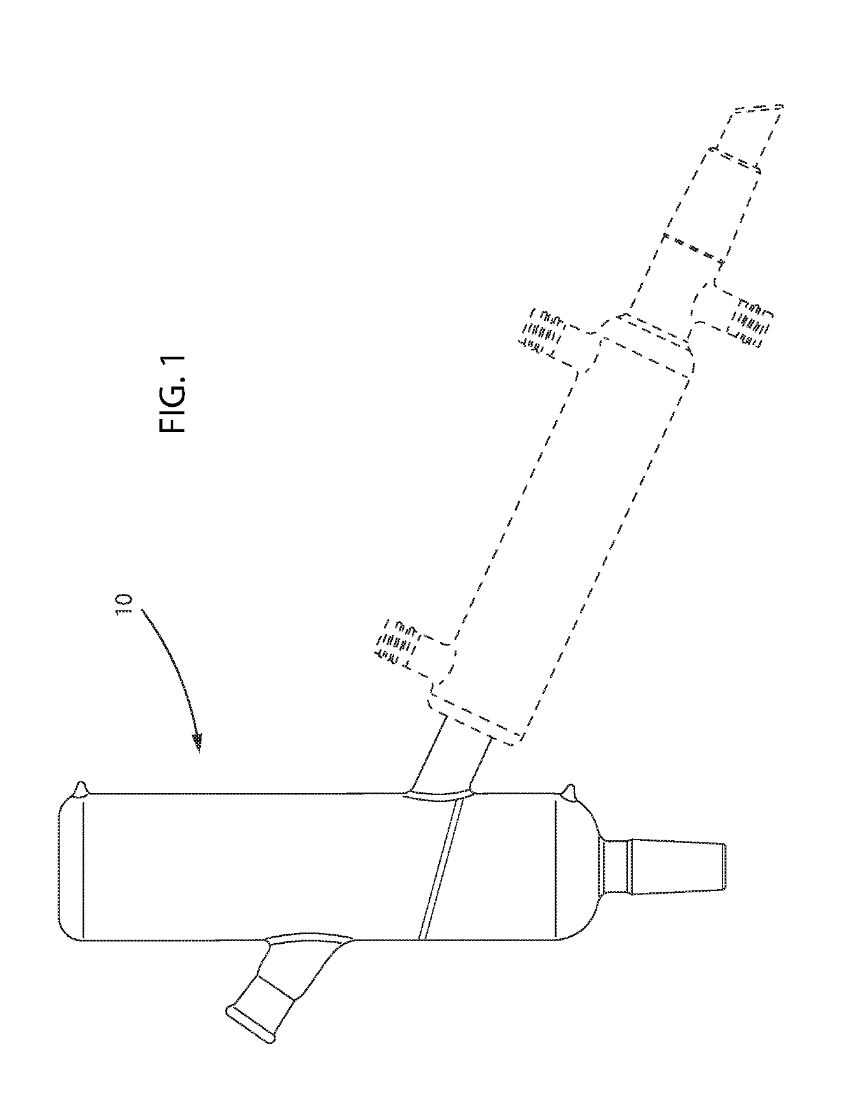
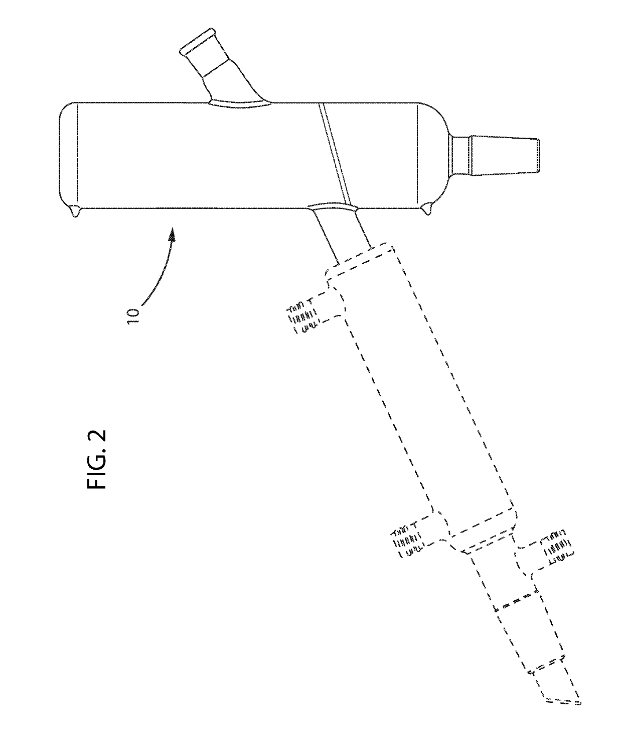
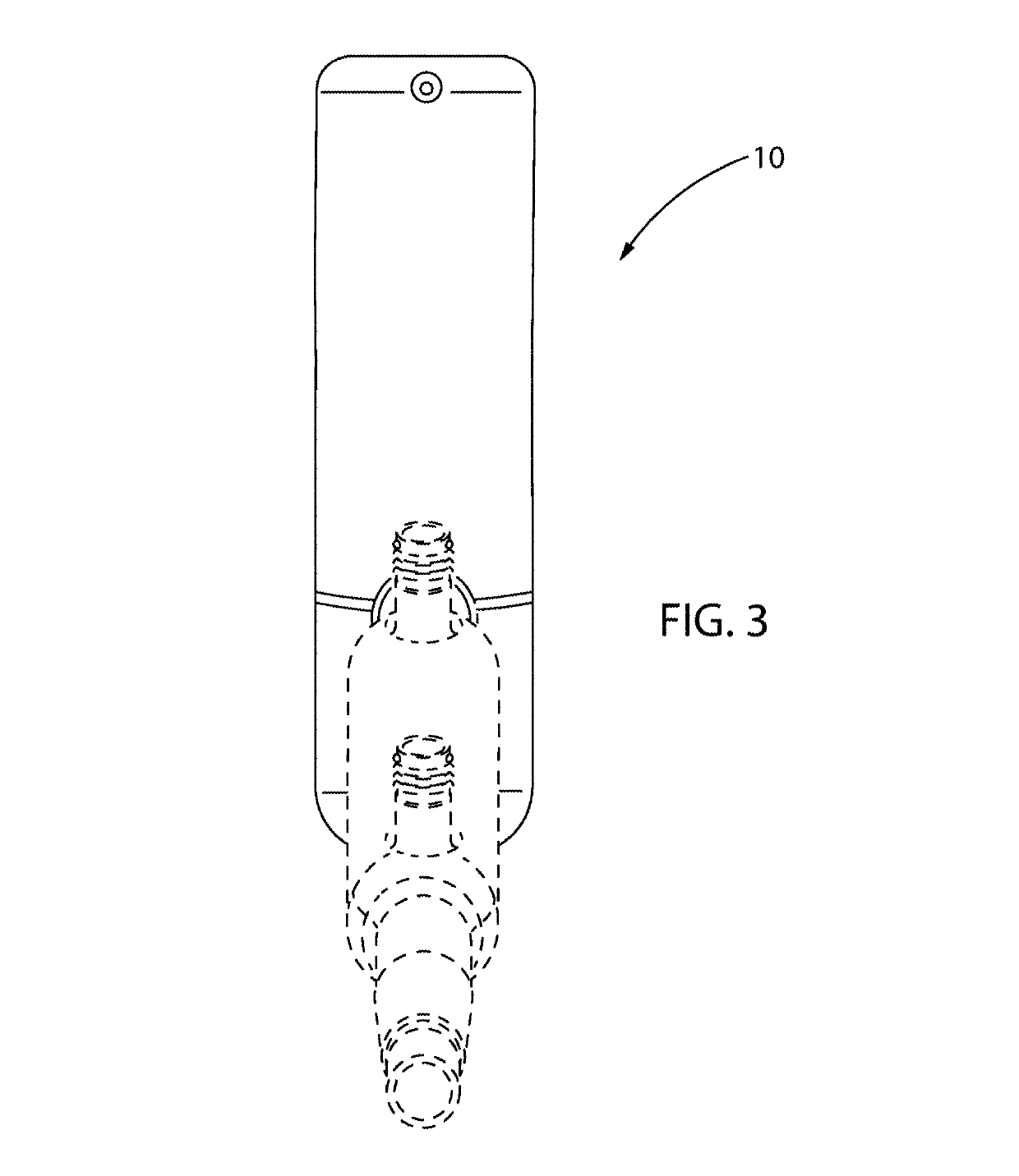
[0032]The distillation head is made up of two main parts: the lower insulated chamber surrounding the fractionating column and the upper insulated chamber surrounding the condenser. The device has heat insulation surrounding the fractionating column, which may be filled with an array of packing materials or structured packings to increase surface area for fractionation. In one embodiment the packing materials are glass beads or any other objects suitable for use in a distillation head that increase the surface area. Once heated by vapor passing through it, the lower insulated chamber contains heat within the fra...


PUM

PropertyMeasurementUnit
temperatureaaaaaaaaaa
outer diameteraaaaaaaaaa

Abstract

A high efficiency distillation head and methods of use has a distillation head that may be used for efficient fractional distillation of high boiling point compounds, and includes a lower insulated jacket surrounding a fractionating column and an upper insulated jacket surrounding a condenser. An exit path of equal or greater cross sectional area to the fractionating column is located at or below the top of the fractionating column.

Description

CROSS-REFERENCE TO RELATED APPLICATIONS[0001]The present application claims priority benefit of U.S. Design patent application No. 29 / 614,928, filed Aug. 24, 2017, and it claims the priority benefit of U.S. Provisional Application No. 62 / 580,032, filed Nov. 1, 2017, the contents of which are incorporated in their entirety herein by reference.BACKGROUND OF THE INVENTION[0002]This disclosure relates to the general field of distillation, and more specifically toward a high efficiency distillation head and methods of use. The distillation head may be used for efficient fractional distillation of high boiling point compounds, and includes a lower insulated chamber (i.e., a jacket or a vacuum jacket) surrounding or wrapped around a fractionating column (also called a path, inner tube, fractionating column, or fractionating tube) and an upper insulated chamber (i.e., a jacket or vacuum jacket) surrounding a condenser. The lower insulated chamber may also feature a vacuum chamber having sil...

Claims


Application Information

Patent Timeline
Patent Type & Authority Patents(United States)
IPC IPC(8): B01D3/16B01D3/02B01D5/00
CPCB01D3/16B01D3/02B01D5/0087B01D5/006B01D5/0003
Inventor MAIBACH, MICHAEL S.
Owner LAB SOC LLC
Why Eureka
Try Eureka