Liquid crystal display device

a display device and liquid crystal technology, applied in semiconductor devices, instruments, horology, etc., can solve the problems of long wires, shortening the wires, and increasing the so as to reduce the required number of source drivers, increase resistance, and improve brightness and chromaticity.

Active Publication Date: 2019-09-10
FUNAI ELECTRIC CO LTD
View PDF13 Cites 38 Cited by
  • Summary
  • Abstract
  • Description
  • Claims
  • Application Information

AI Technical Summary

Benefits of technology

The patent aims to solve the problem of variance in brightness and chromaticity on liquid crystal display panels caused by longer wires and higher resistance. The invention provides a solution to prevent this issue and ensure consistent display quality.

Problems solved by technology

As the display panels used in liquid crystal display devices have become larger in recent years, the wires (source lines) from the signal generator (source driver) to the input ends of the pixels of the display panel tend to become longer.
Thus, the output ends of a single source driver have to be connected to input ends of the pixels of the display panel that are farther away, which makes the wires become longer.

Method used


Image

  • Liquid crystal display device
  • Liquid crystal display device
  • Liquid crystal display device

Examples


first embodiment

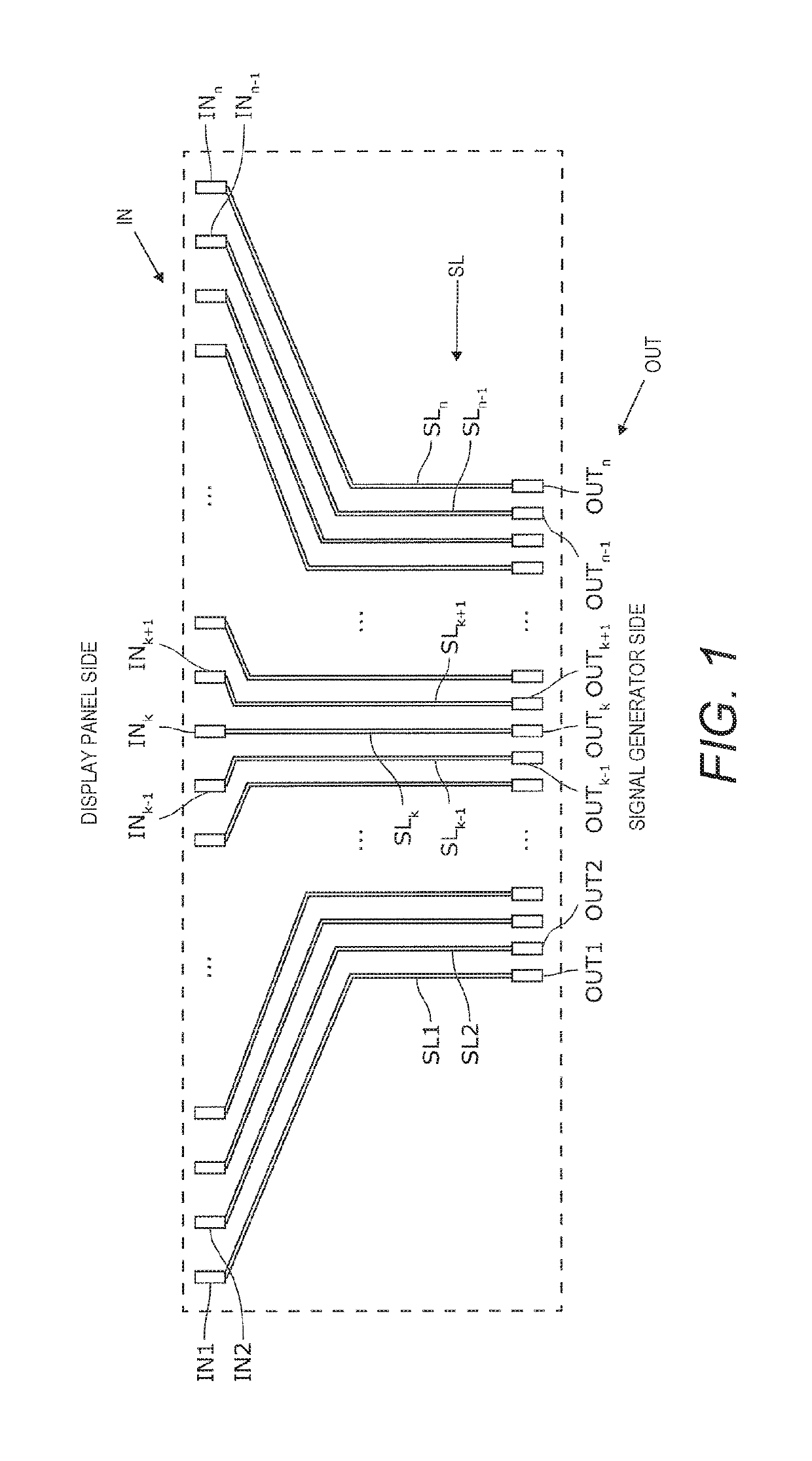
[0035]A liquid crystal display device 1 in accordance with a first embodiment will be described through reference to FIGS. 1 to 8. FIG. 1 is a schematic diagram of a plurality of wires SL that spread out in a fan shape and connect a display panel 10 and a signal generator 20 of the liquid crystal display device 1.

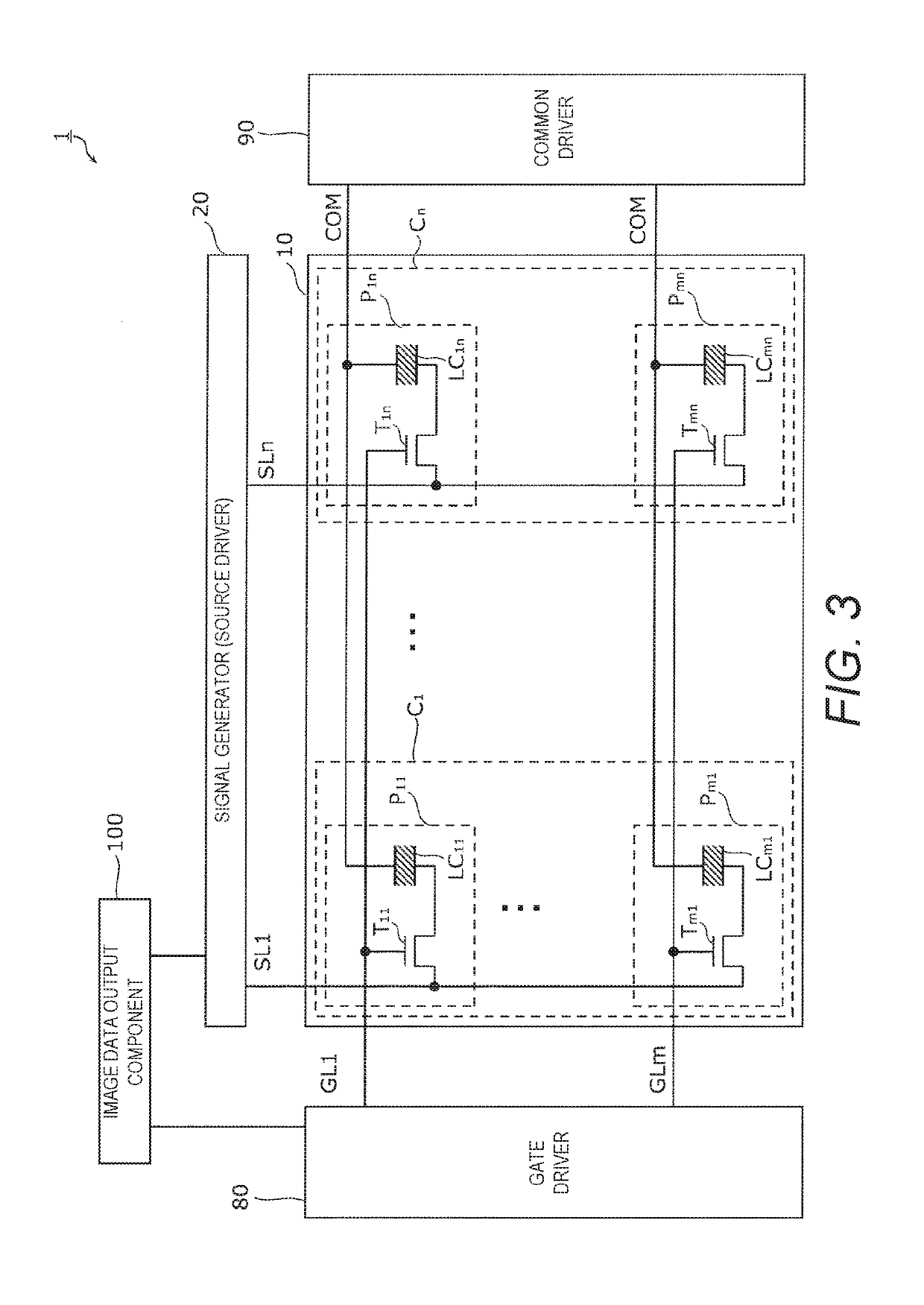
[0036]As shown in FIG. 1, the wires (source lines) SL connect the output ends OUT (such as output terminals) of the signal generator (source driver) 20 to the input ends IN (such as input terminals) corresponding to a plurality of pixels Pij (i=1 to m, j=1 to n) (see FIG. 3) of the display panel 10. The signal generator 20 supplies data signals to the pixels Pij of the display panel 10 through the wires SL. Herein, the output ends OUT of the signal generator 20 will also be called simply output ends OUT, and the input ends IN corresponding to the pixels Pij will also be called simply input ends IN. In general, the pitch of the input ends IN is greater than the pitch of the ...

second embodiment

[0093]Referring now to FIGS. 9 to 13B, a liquid crystal display device 1 in accordance with a second embodiment will now be explained. In view of the similarity between the first and second embodiments, the parts of the second embodiment that are identical to the parts of the first embodiment will be given the same reference numerals as the parts of the first embodiment. Moreover, the descriptions of the parts of the second embodiment that are identical to the parts of the first embodiment may be omitted for the sake of brevity.

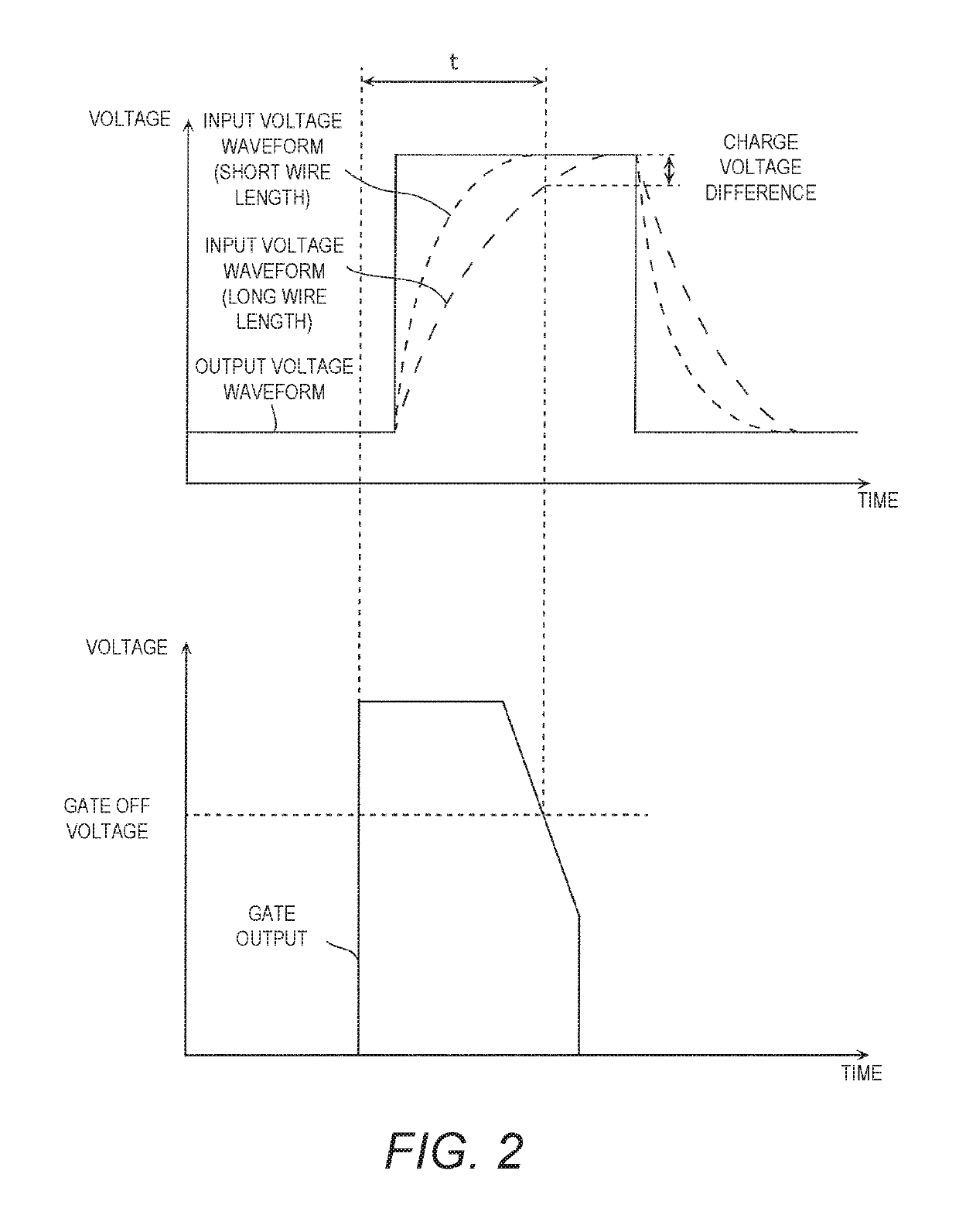
[0094]With the above-mentioned liquid crystal display device 1 in accordance with the first embodiment, the low-pass filters, the buffers, or other such current controllers 31 reduce variance in the input voltage waveform at the input ends IN. The current controllers 31 are built into the signal generator 20 and are connected to the output ends OUT. In particular, the current controllers 31 are prepared for a particular display panel 10 in which the lengths o...

third embodiment

[0125]Referring now to FIGS. 14 to 18B, a liquid crystal display device 1 in accordance with a third embodiment will now be explained. In view of the similarity between the first to third embodiments, the parts of the third embodiment that are identical to the parts of the first and second embodiments will be given the same reference numerals as the parts of the first and second embodiments. Moreover, the descriptions of the parts of the third embodiment that are identical to the parts of the first and second embodiments may be omitted for the sake of brevity.

[0126]The liquid crystal display device 1 in accordance with the third embodiment is basically identical to the liquid crystal display device 1 in accordance with the first embodiment, except that the liquid crystal display device 1 in accordance with the third embodiment it includes a signal generator 20b instead of the signal generator 20, and a controller 40 on the outside of the signal generator 20b, for example. The rest o...


PUM

PropertyMeasurementUnit
resistanceaaaaaaaaaa
wire resistanceaaaaaaaaaa
voltageaaaaaaaaaa

Abstract

A liquid crystal display device includes a display panel, a signal generator, a plurality of wires, and a controller. The display panel has a plurality of pixels. The signal generator supplies data signal to the pixels. The wires connect output ends of the signal generator to input ends of the pixels, respectively. The controller varies voltage waveform corresponding to the data signal at the output ends by varying both a voltage level at a rising edge of the voltage waveform and a voltage level at a falling edge of the voltage waveform.

Description

CROSS-REFERENCE TO RELATED APPLICATIONS[0001]This is a continuation application of U.S. patent application Ser. No. 15 / 653,416 filed on Jul. 18, 2017, which claims priority to Japanese Patent Application No. 2016-145544 filed on Jul. 25, 2016. The entire disclosures of U.S. patent application Ser. No. 15 / 653,416 and Japanese Patent Application No. 2016-145544 are hereby incorporated herein by reference.BACKGROUNDField of the Invention[0002]The present invention generally relates to a liquid crystal display device.Background Information[0003]A tri-gate structure or a dual-gate structure has been used in recent years as a cell drive system for liquid crystal display devices. With a tri-gate structure, for example, signals are simultaneously applied to three pixels via data lines from a signal generator (source driver). Thus, the required number of source drivers can be reduced, which can lower the cost. Japanese Laid-Open Patent Application Publication No. 2006-338012 (Patent Literatu...

Claims


Application Information

Patent Timeline
Patent Type & Authority Patents(United States)
IPC IPC(8): H01L27/12G02F1/1335G04G9/00G09G3/36G02F1/136
CPCH01L27/124G02F1/1335G04G9/0035G09G3/3685G09G3/3688G09G2320/0233G02F1/136G09G3/36G09G2320/0223G09G3/3696
Inventor ISHIDA, TOSHIYUKIIDE, KENTA
Owner FUNAI ELECTRIC CO LTD
Why Eureka
Try Eureka