
Equipment enclosure air flow control system

a technology for controlling system and equipment, which is applied in ventilation systems, lighting and heating apparatus, heating types, etc., can solve the problems of wasted energy, poor optimization of cooling, and waste of space in rack enclosures

Active Publication Date: 2019-09-10
INT BUSINESS MASCH CORP
View PDF18 Cites 0 Cited by
  • Summary
  • Abstract
  • Description
  • Claims
  • Application Information

AI Technical Summary

Benefits of technology

Enables efficient and automated control of air flow, temperature, and pressure, optimizing cooling and reducing energy waste by accommodating diverse IT equipment needs within a single enclosure design.

Problems solved by technology

This can lead to wasted space in the rack enclosure, poor optimization of the cooling, wasted energy and IT resource risks.

Method used


Image

  • Equipment enclosure air flow control system
  • Equipment enclosure air flow control system
  • Equipment enclosure air flow control system

Examples


Embodiment Construction

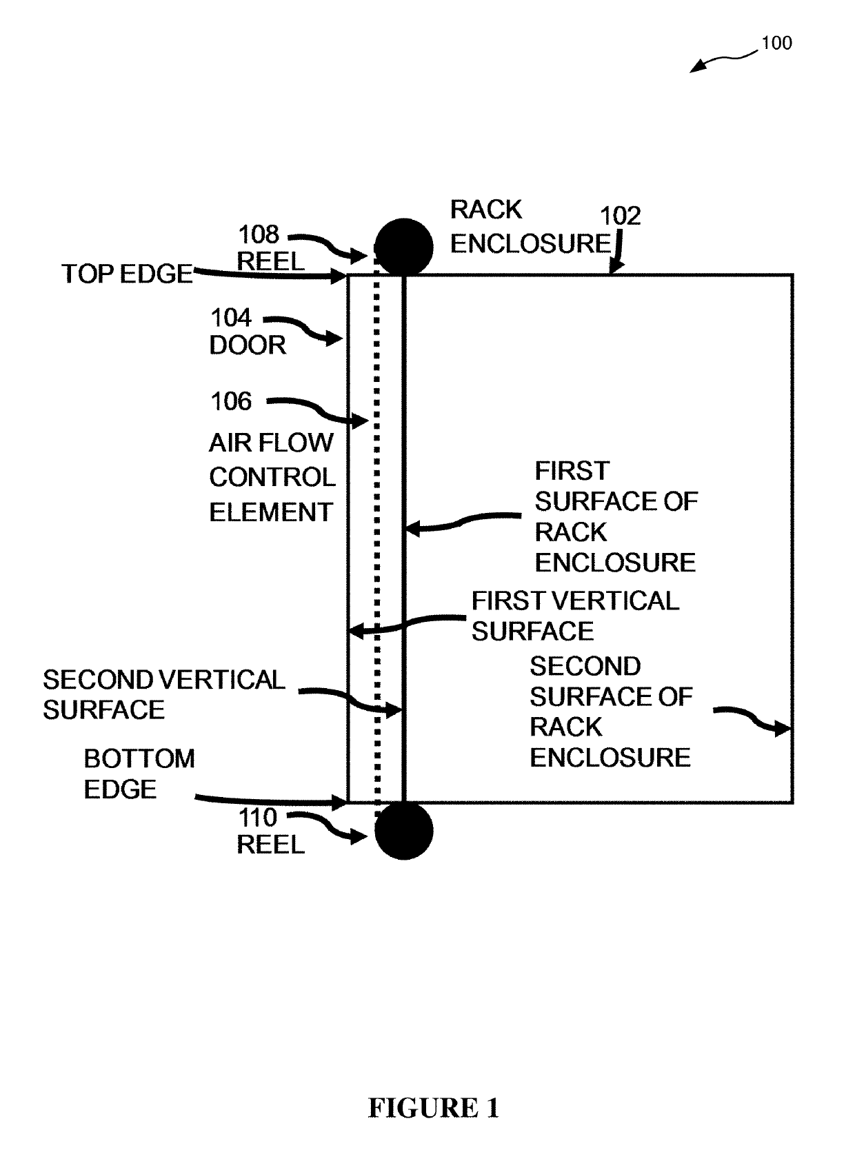
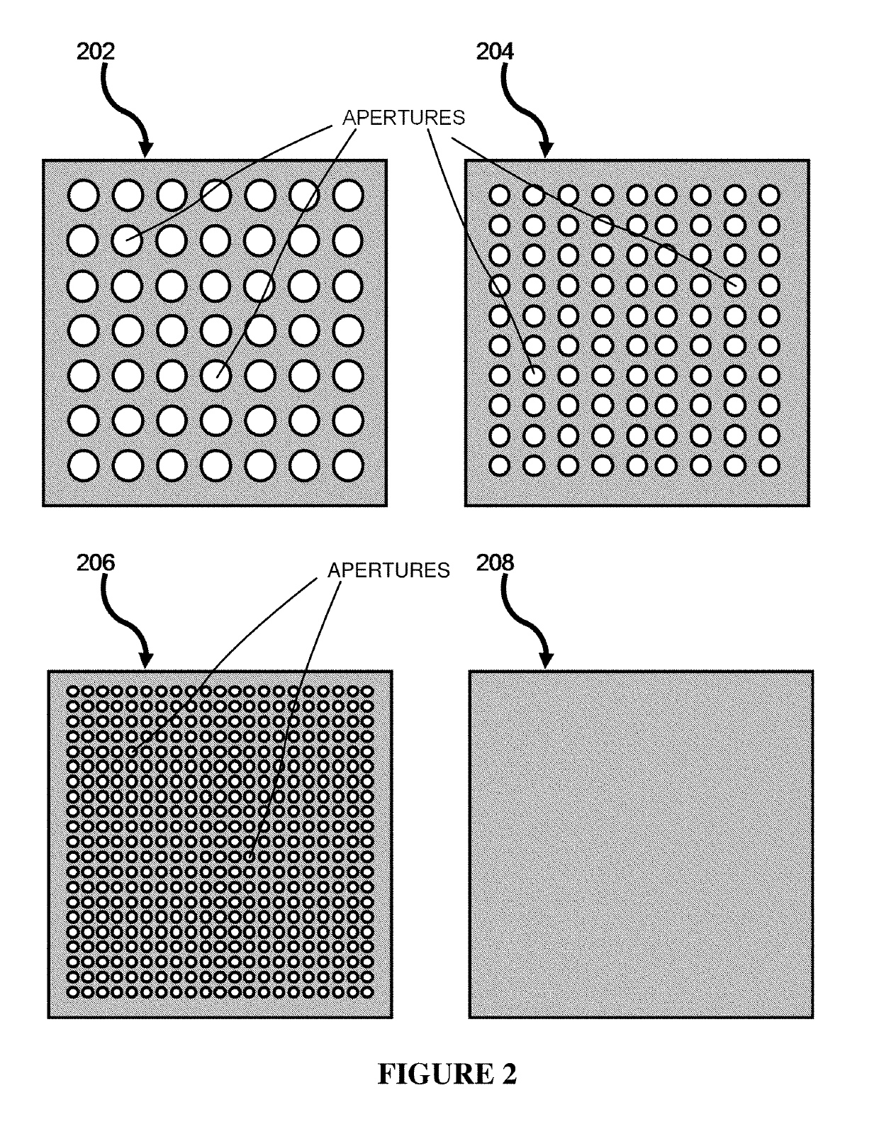
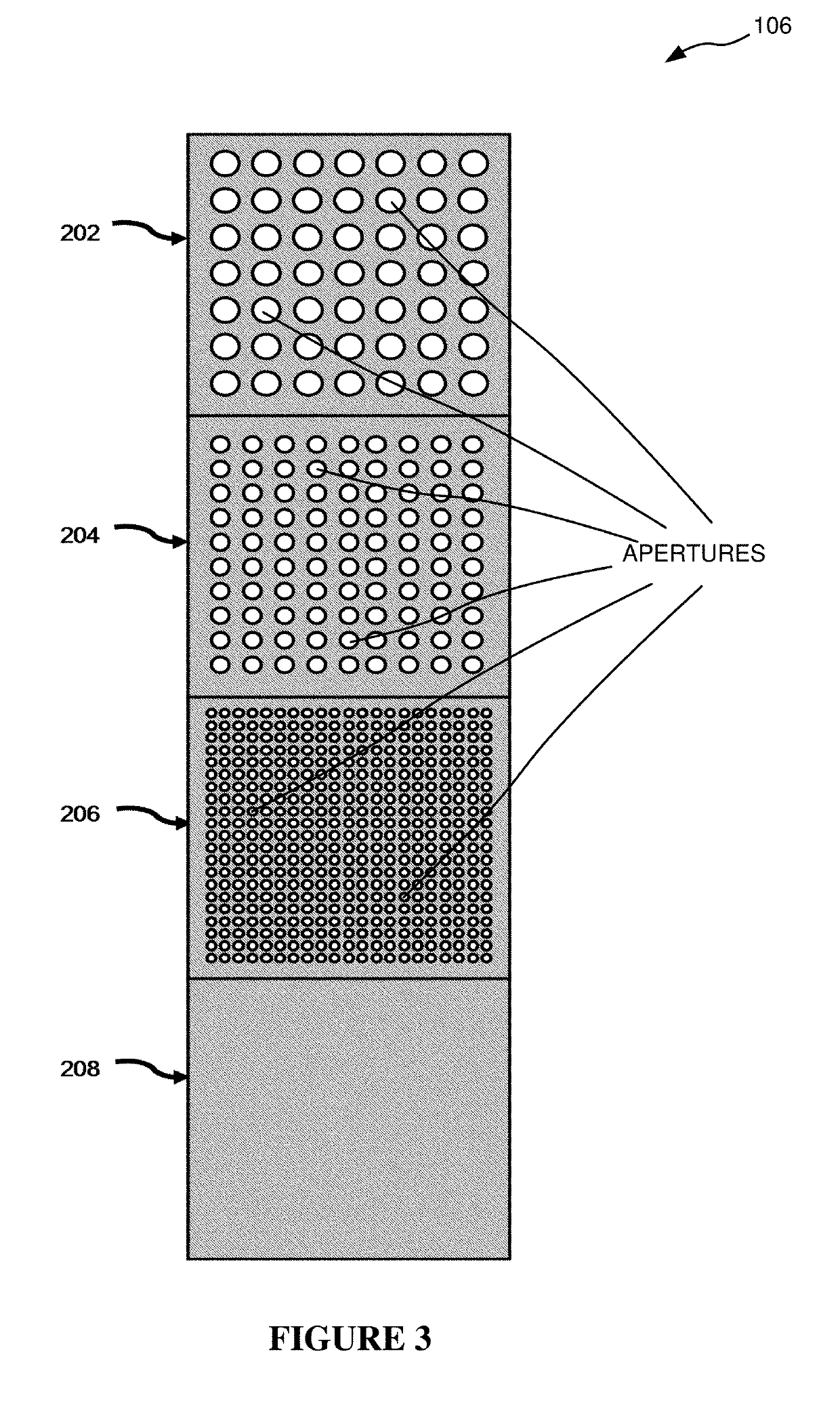
[0023]FIG. 1 shows an air flow control system according to a first embodiment of the present invention positioned on a rack enclosure 102. The air flow control system has a first reel 108 and a second reel 110 located along opposing first and second edges of the rack enclosure door 104. Between the first reel 108 and the second reel 110 is a first air flow control element 106. The first air filter control element 106 has a length sufficient to allow movement of the first air flow control element 106 from reel 108 to reel 110 to allow at least two different portions (202, 204, 206, 208 of FIG. 2) to be able to be positioned across the rack enclosure door 104. First reel 108 and second reel 110 are located, respectively, along a top edge and a bottom edge of first door 104, with first air flow control element 106 (i) being located between first reel 108 and second reel 110, (ii) being located between a first vertical surface of first door 104 and a second vertical surface of first doo...


PUM


Abstract

Disclosed is a system and method for control of air flow in an enclosure. A system discloses: a first element located on a first surface of the equipment enclosure having: first and second reels located along opposing edges of the first element; and a first air flow control element located between first and second reels and having a first portion and a second portion, said first portion being located on an edge of the first element adjoining the first reel, said second portion being located on an edge of the first element adjoining the second reel, each having apertures located therein of a number or cross sectional area different from the other portions, movement of the first air flow control element from a first reel to a second reel by rotation of the reels causing the first portion or second portion to be positioned between the first and second reels.

Description

FIELD OF THE INVENTION[0001]The present invention relates to the control of air flow in an equipment enclosure, and more particularly, to the control of air flow in an equipment enclosure through the use of a moveable air flow control element having a plurality of portions, each portions having apertures of a number or cross sectional area different from the apertures of other portions.BACKGROUND[0002]Different Information Technology (IT) resources in equipment enclosures require different air flow and air pressure for cooling of the resources. Conventionally, each of the equipment enclosures hosted by a data center needs to have a specific door physically designed and adapted to the content of equipment in the equipment enclosure and its corresponding different air flow and air pressure requirements. Typically, the equipment is mounted in a rack enclosure having a front door for access to equipment in the rack enclosure and, optionally, a back door, also allowing access to the equi...

Claims


Application Information

Patent Timeline
Patent Type & Authority Patents(United States)
IPC IPC(8): F28F13/08H05K7/20
CPCH05K7/20836H05K7/20745H05K7/20736F24F7/00F24F11/0001F24F11/74F24F2007/0025H05K7/20H05K7/20145H05K7/20709
Inventor RODRIGUEZ, JEAN-MICHEL
Owner INT BUSINESS MASCH CORP
Features
  • Generate Ideas
  • Intellectual Property
  • Life Sciences
  • Materials
  • Tech Scout
  • Unparalleled Data Quality
  • Higher Quality Content
  • 60% Fewer Hallucinations
Learn More