See through display enabling the correction of visual deficits

a technology of visual deficit and display system, applied in spectacles/goggles, instruments, spectacles/goggles, etc., can solve the problems of not being able to correct for multiple objects at varying focal distances, many are opaque, and cannot be able to achieve the correction of visual deficits, so as to maximize the transmission of light, increase the level of sound differentiation, and reduce the effect of power consumption

Inactive Publication Date: 2019-09-17
IRON CITY MICRO DISPLAY INC
View PDF11 Cites 0 Cited by
  • Summary
  • Abstract
  • Description
  • Claims
  • Application Information

AI Technical Summary

Benefits of technology

[0030]This invention further intends to accomplish this by a data circuit loop whereby the visual field is captured by the image sensors, the video data is modulated by a processing unit to suit the user's specific needs such as presbyopia (inability to focus on near and far objects because of hardening of lens), and then this modified visual field is projected onto a display positioned in front of the user's eyes. The processor may be single or multi-part and communicate with each other through wired or wireless means. The image processing is expected to consume significant calculation resources in both power and processor and therefore, the wireless communication of the processing units enables the outsourcing of calculations to be done on a unit positioned outside the actual image capture and display apparatus.
[0031]To enable usage in daily life, the display lens of the apparatus is created in such a way that maximizes the transmission of light so that the user has a natural view of the outside field of view when the projector is not displaying an image.
[0032]This apparatus specifically incorporates a safety feature whereby the outer margin of the user's visual field is left intentionally intact without obstruction by the display lens or the display projection area. This enables the user to maintain visual cues from the peripheral vision which is useful for depth perception, motion detection in the periphery, and other spatial awareness cues that enable natural walking and activities of daily living.
[0033]The sound sensor may be single or multiple with audio capture apparatus on the surface of the apparatus, or positioned in a tube. The tube may or may not be pointed in-line with the user's visual field. The purpose of this orientation includes the optimization and differentiation of audio inputs to the user's attention. By orienting a tube in front of the audio sensor that is in-line with the user's visual field, sound inputs that coming from the front of the user will selectively be captured, thereby increasing the level of sound differentiation.
[0036]The presence of multiple sound sensors enables different audio signals to flow into the processor. The processor can compare the audio inputs and distinguish sound of interest while modulating ambient sound or noise. For example, consider a head-mounted apparatus with 4 total audio sensors, two positioned in forward facing tubes, and two others on the surface of the apparatus. Surface audio sensors will detect the most sound; however, the sensor cannot distinguish between ambient noise from an air conditioner and a person speaking in front of the user. The audio sensor-processor-speaker system may increase the absolute value of the audio inputs, but contrast between the ambient noise and forward speaker will not change, and the user will have difficulty discerning the words spoken in front. Audio sensors positioned within a tube pointed forward will selectively sense sound from the front. With both types of inputs, surface and tubular, the processor can compare the signals and identify what is noise and what is sound from the front. If there is a significant discrepancy, the processor can selectively amplify the forward sounds and diminish the surface sounds, thereby enabling the user to better distinguish sounds from the front from ambient noise. This invention is not restricted to this four sensor system, however, intends to capture the merits of sound spatial selectivity as described here.PRIOR ARTS
[0045]In recent years, there have been registered patents such as U.S. Pat. No. 7,145,571 by Jones et al., “Technique for enabling color blind persons to distinguish between various colors,” which seek to create solutions that enable people with color blindness to distinguish between objects by means other than color such as hue and patterns. FIG. 13 shows an image from the aforementioned patent. Patterns are matched to colors, and image data is modified to show these patterns in lieu of colors, thereby circumventing the patient's color vision deficit and leveraging the ability to distinguish black and white vision. Our invention is fundamentally different because we seek to harness the weakened but present ability in a patient with color blindness who are not truly blind, but can sense the color if intensity is significantly increased.

Problems solved by technology

Many inventors have developed wearable displays, but many are opaque; users can see the display, but cannot see through it.
Levola in SID 2006 Digest, ISSN0006-64 • SID 06 DIGEST 0966X / 06 / 3701-0064, Novel Diffractive Optical Components for Near to Eye Displays discloses an example of implementation of see through display, locating LCD device in the middle of two eyes, but still this does not correct for visual deficits of focal distances.
This system also has the same configuration as the above prior art and cannot correct for multiple objects at varying focal distances.
This system will not be able to correct for multiple objects of varying focal distances.
However, none of these prior arts seek to create an image sensory and display apparatus that modulates captured image data by modifying the focal distance of multiple objects and displays them for the viewer.

Method used


Image

  • See through display enabling the correction of visual deficits
  • See through display enabling the correction of visual deficits
  • See through display enabling the correction of visual deficits

Examples


Embodiment Construction

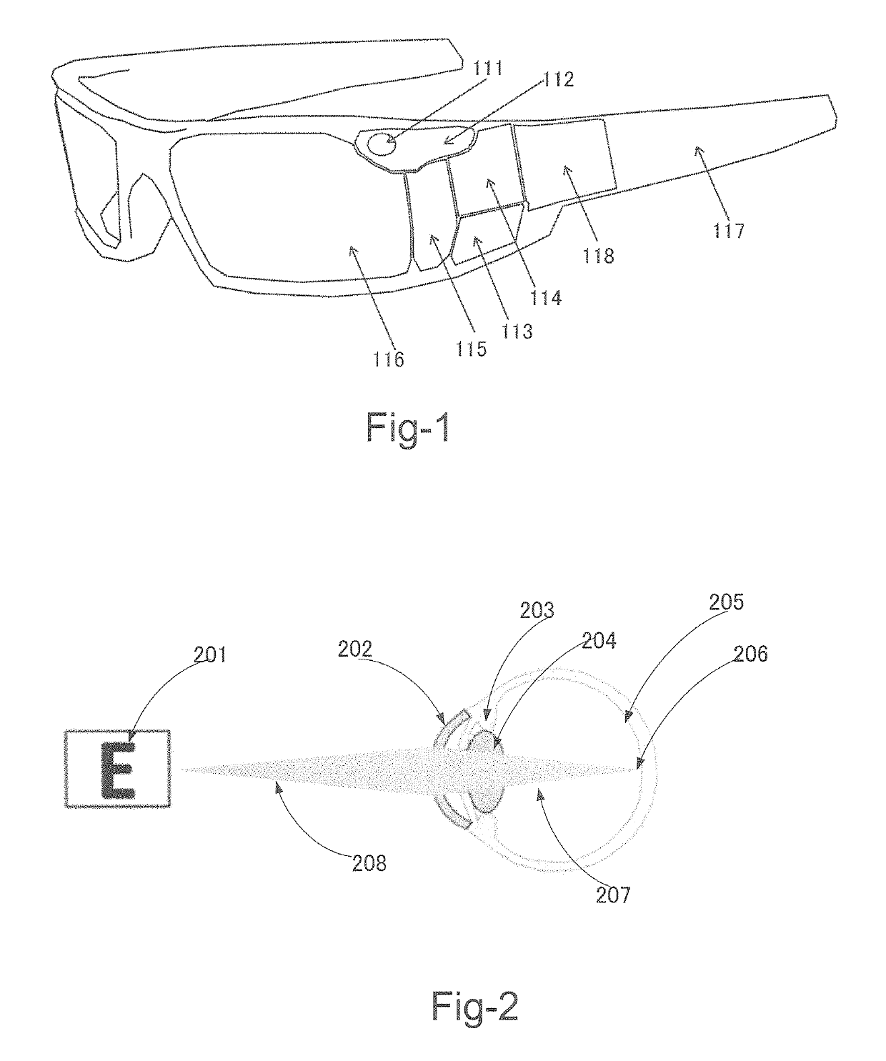
[0076]This invention seeks to create such a visual sensory and display system via a visual image data flow as depicted in FIG. 17 through 20. Cameras are mounted onto a set of glasses pointed in-line with the user's visual field. The cameras convert visual images into image data, which is then sent to a modulation system where the image data is divided into specific focal distances. The modulation system may relay this information back to the camera to recapture the image through an optical focusing system, or the modulator may focus the object through digital algorithms. The modulator will ultimately output digital image data with objects with focal distances for multiple objects recalibrated to a distance that the viewer can readily perceive.

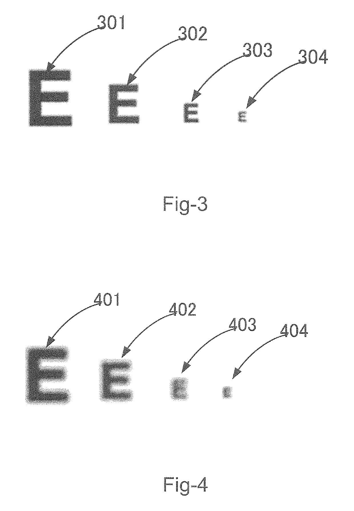
[0077]FIG. 17 shows an example of the embodiments of this invention with a hypothetical visual field with multiple objects with varying focal distances. The camera (1701) captures the objects (901, 902, 903 and 904 in FIG. 9) in various distan...


PUM


Abstract

A See-Through Display System with the ability to correct visual deficits such as presbyopia, color blindness and poor night vision is disclosed. This invention enables the correction of visual deficits using camera(s), microdisplay (s), controlling circuit(s) with digital grayscale control and see through optics such as free form lens / mirror, half-mirror, diffractive and / or holographic optical element(s).

Description

CROSS REFERENCE TO RELATED APPLICATIONS[0001]This application is a Continuation in Part application of U.S. application Ser. No. 14 / 121,588 filed on Sep. 21, 2014 and application Ser. No. 14 / 121,588 is a Non-Provisional application and claims the Priority Date of previously filed Provisional Application 61 / 960,537 filed on Sep. 21, 2013.TECHNICAL FIELD[0002]This invention relates to a wearable visual sensor-modulator-display system that (1) is worn on a user's head or face, (2) has a single or multiple visual sensors, (3) has a video image modulator, and (4) projects a video image via a microdisplay to the user's visual field. More particularly, this invention relates to the application of aforementioned display system to acquire visual imagery, modulate the video image in a manner that corrects for visual deficits and displays the visual imagery in a manner that the user can perceive and differentiate.BACKGROUND OF THE INVENTION[0003]Humans have various medical conditions that alte...

Claims


Application Information

Patent Timeline
Patent Type & Authority Patents(United States)
IPC IPC(8): G02B27/02G02B27/01F21V8/00G02C11/00G09B21/00
CPCG02B6/0035G02C11/10G02B27/0172G09B21/008G02B27/027G02C2202/10G02B2027/0174G02B2027/0127G02B2027/014G02B2027/0118G02B2027/0138G02B2027/0178G02B2027/0112
Inventor STONE, VICTORISHII, FUSAO
Owner IRON CITY MICRO DISPLAY INC
Why Eureka
Try Eureka