
Hydroelectricity generating unit capturing marine current energy

a technology of hydroelectricity and current energy, applied in the direction of machines/engines, vessels, transportation and packaging, etc., can solve the problems of untapped potential, high cost, and inability to meet the needs of new hydroelectric construction projects,

Active Publication Date: 2019-09-24
GEHRING DONALD HOLLIS
View PDF36 Cites 6 Cited by
  • Summary
  • Abstract
  • Description
  • Claims
  • Application Information

AI Technical Summary

Benefits of technology

The present invention is about a pontoon barge that can generate power from marine currents. The invention is designed to be installed in various water depths and can use a variety of mooring methods. The invention can be used to generate power in areas where there are no existing dams or reservoirs, and can even be used to support new bridges across tidal estuaries or rivers. The invention can be quickly and safely installed and maintained with low-cost methods. The technical effect of the invention is to provide a new and effective way to generate power from marine currents, which is a renewable and cost-effective source of energy.

Problems solved by technology

However, power from new hydroelectric construction projects is not as cost effective as from existing facilities and much more time consuming especially regarding the permitting process to flood new areas for reservoirs.
This makes ocean currents a promising source of hydroelectric power which is largely untapped and virtually unlimited in potential.

Method used


Image

  • Hydroelectricity generating unit capturing marine current energy
  • Hydroelectricity generating unit capturing marine current energy
  • Hydroelectricity generating unit capturing marine current energy

Examples


second embodiment

[0037]In reference to the present invention, the torque transmission system 32 comprises a port-side driver pulley 37, a port-side driven pulley 38, a port-side belt 39, a starboard-side driver pulley 40, a starboard-side driven pulley 41, and a starboard-side belt 42 as shown in FIG. 9-10. More specifically, the main axle 14 for the at least one paddle wheel assembly 13 is torsionally connected to the port-side driver pulley 37 and positioned adjacent to the port-side section 3 from one side. The main axle 14 for the at least one paddle wheel assembly 13 is torsionally connected to the starboard-side driver pulley 40 and positioned adjacent to the starboard-side section 4 from opposite side. The first connector axle 26 is torsionally connected to the port-side driven pulley 38 and positioned adjacent to the port-side section 3. The second connector axle 27 is torsionally connected to the starboard-side driven pulley 41 and positioned adjacent to the starboard-side section 4. The po...

third embodiment

[0040]In reference to the present invention, the torque transmission system 32 comprises a port-side driver gearbox 43, a port-side driven gearbox 44, a port-side drive axle 49, a starboard-side driver gearbox 45, a starboard-side driven gearbox 46, and a starboard-side drive axle 50 as shown in FIG. 11-13. More specifically, the main axle 14 for the at least one paddle wheel assembly 13 is torsionally connected to an input gear 47 of the port-side driver gearbox 43 and positioned adjacent to the port-side section 3 from one side. The main axle 14 for the at least one paddle wheel assembly 13 is torsionally connected to an input gear 47 of the starboard-side driver gearbox 45 and positioned adjacent to the starboard-side section 4 from opposite side. The first connector axle 26 is torsionally connected to an input gear 47 of the port-side driven gearbox 44 and positioned adjacent to the port-side section 3. The second connector axle 27 is torsionally connected to an input gear 47 of...

fourth embodiment

[0043]In reference to the present invention, the torque transmission system 32 comprises a first port-side gearbox 51, a second port-side gearbox 52, a first starboard-side gearbox 53, and a second starboard-side gearbox 54 as shown in FIG. 14-16. The at least one generator assembly 20 further comprises a linear set of port-side generators 30 and a linear set of starboard-side generators 31. More specifically, the main axle 14 for the at least one paddle wheel assembly 13 is torsionally connected to an input gear 47 of the first port-side gearbox 51 and positioned adjacent to the port-side section 3 from one side. The main axle 14 for the at least one paddle wheel assembly 13 is torsionally connected to an input gear 47 of the first starboard-side driver gearbox 45 and positioned adjacent to the starboard-side section 4 from opposite side. The linear set of port-side generators 30 is positioned along the port-side section 3. The linear set of starboard-side generators 31 is position...


PUM


Abstract

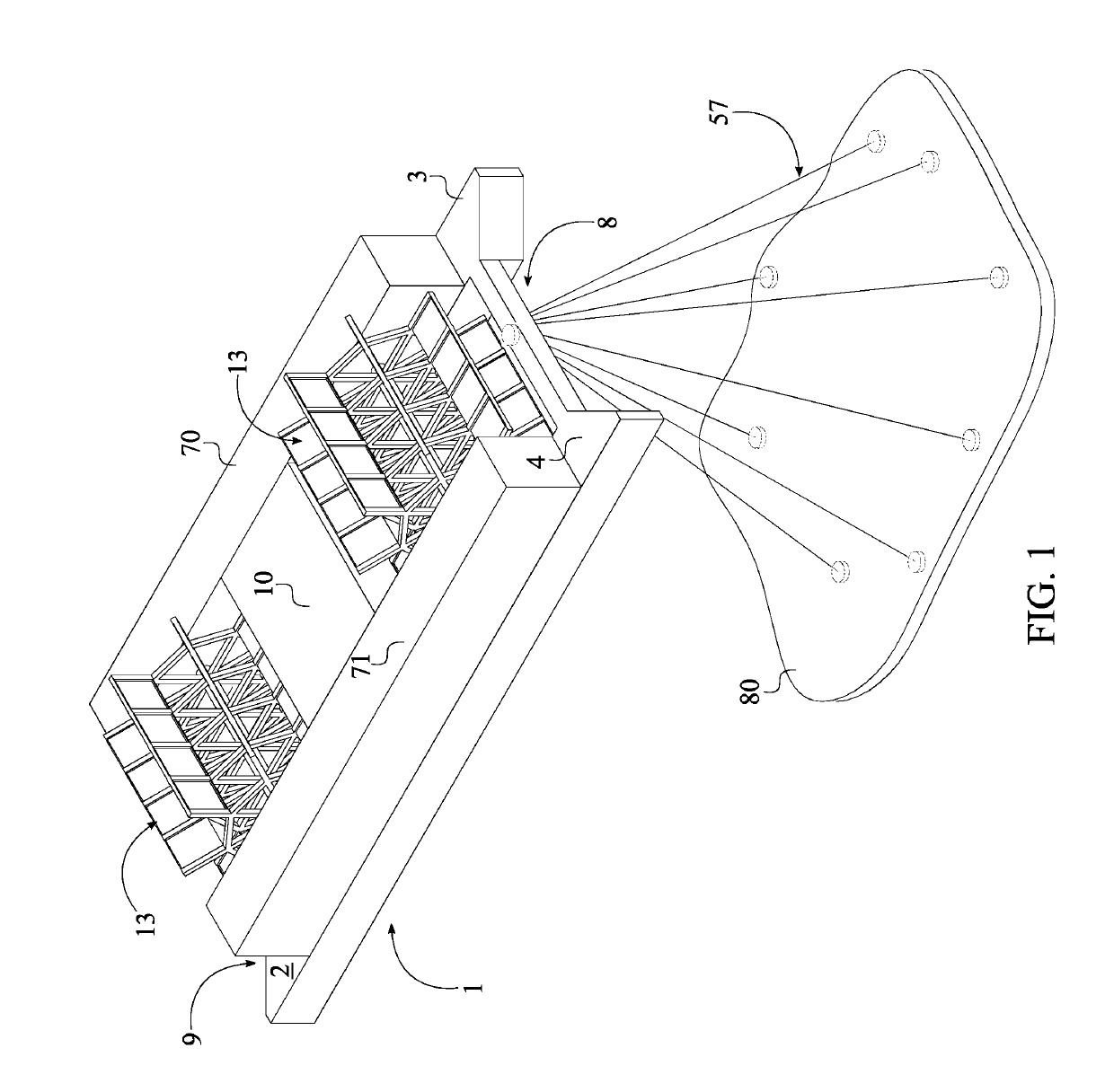
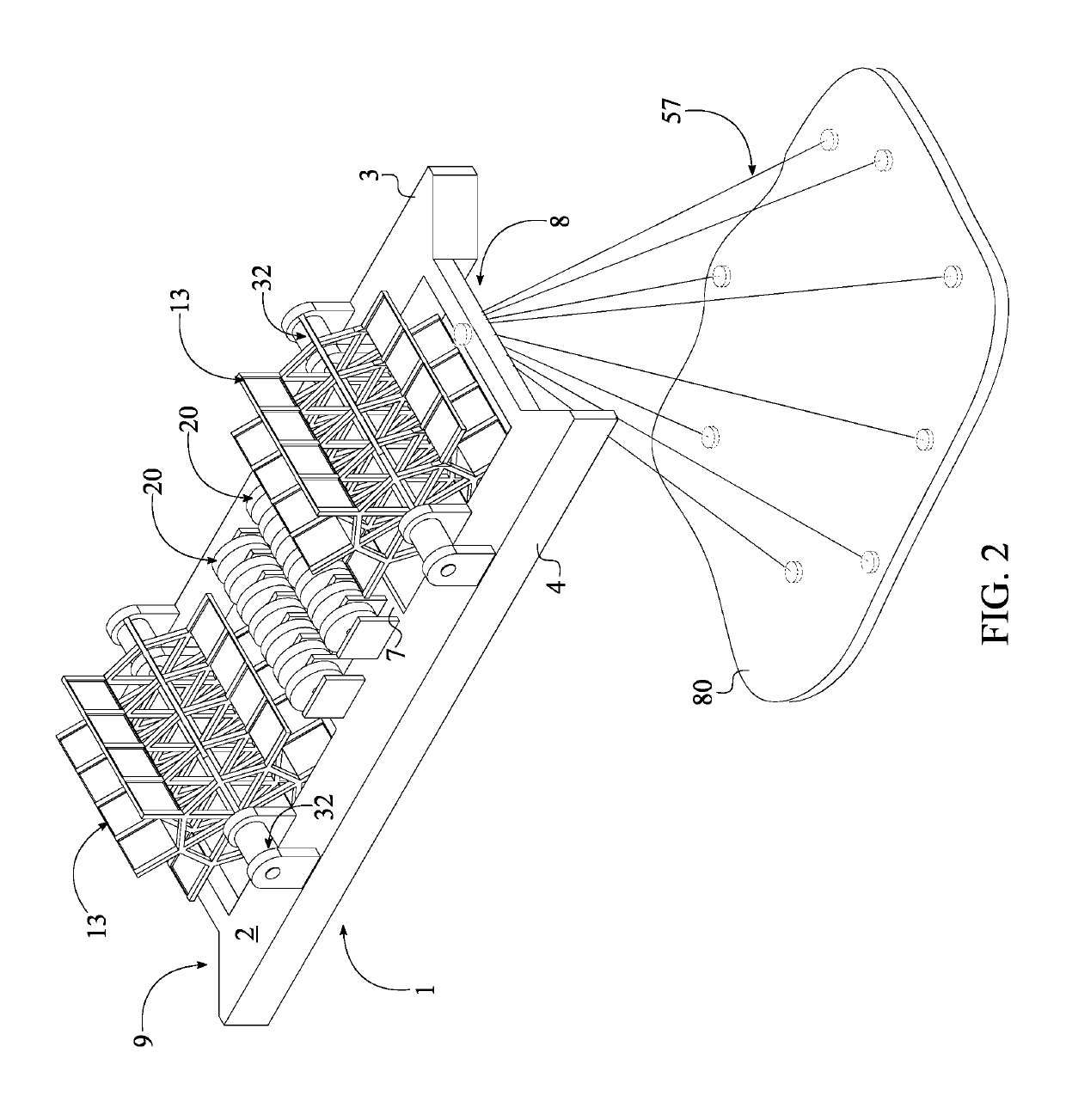
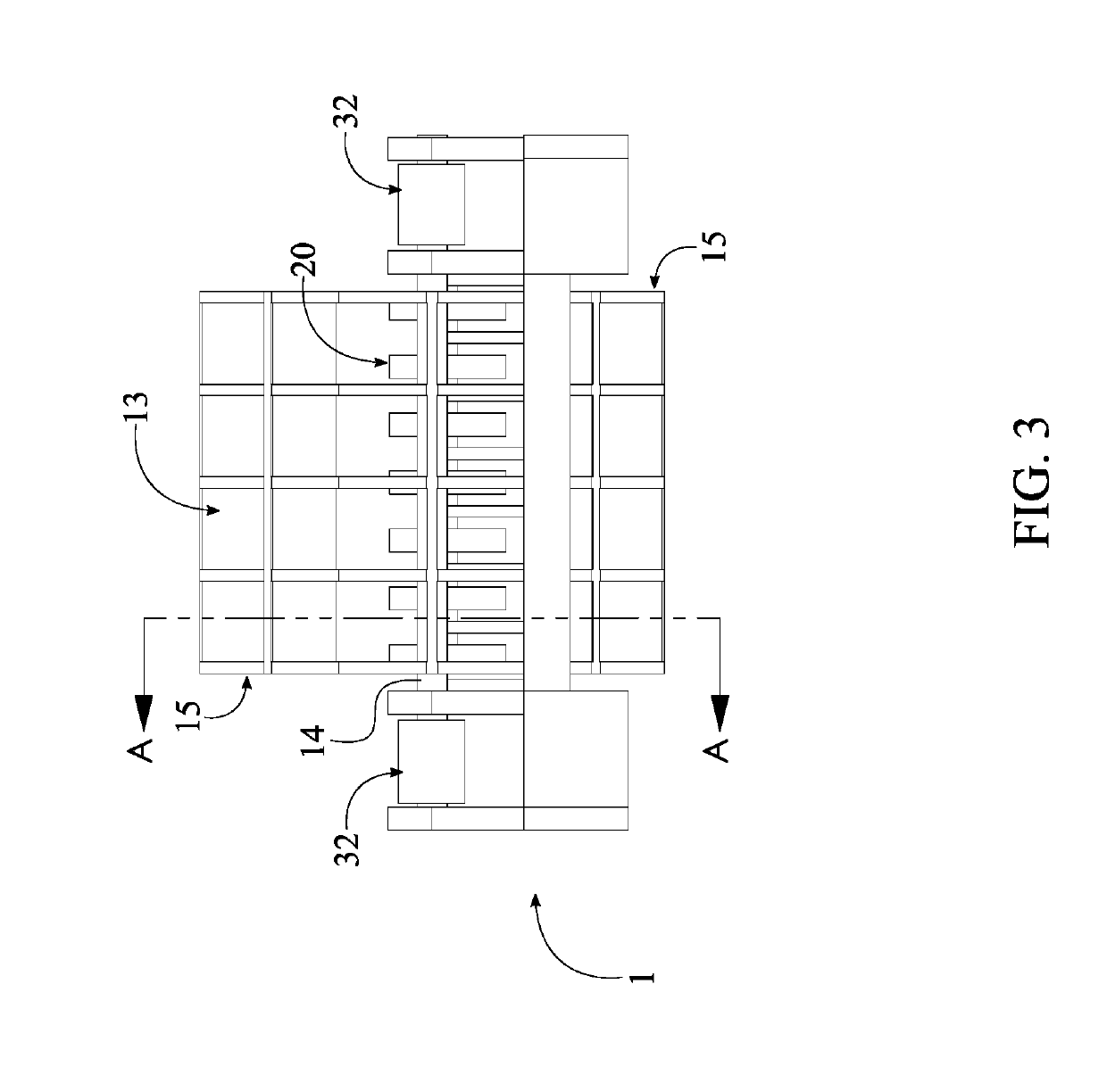
A hydroelectricity generating unit capturing marine current energy includes a floating hull, at least one paddle wheel assembly, at least one generator assembly, a torque transmission system, and an anti-drift mooring system. The at least one paddle wheel assembly is rotatably mounted to the floating hull and operatively coupled with the at least one generator assembly by the torque transmission system, wherein a kinetic energy of the at least one paddle wheel assembly is transferred to the at least one generator assembly by the torque transmission system to generate hydroelectricity. The torque transmission system can be a hydraulic system, a pulley system, a multiple gearbox system, or a direct driveshaft. The floating hull is tensionably coupled to a subsurface environment by the anti-drift mooring system, enabling the least one paddle wheel assembly to capture water current.

Description

[0001]The current application claims a priority to the U.S. Provisional Patent application Ser. No. 62 / 514,625 filed on Jun. 2, 2017. The current application is filed on Jun. 4, 2018 while Jun. 2, 2018 was on a weekend.FIELD OF THE INVENTION[0002]The present invention relates generally to power generation, and more specifically to pontoon barges that support one or more paddlewheels turned by water currents to generate power.BACKGROUND OF THE INVENTION[0003]As technology and industry in the modern world continues to grow and expand, so do the power requirements. Many different sources of power generation exist today involving: fossil fuel burning, solar, wind, geothermal, hydroelectric, wave and current power generation, etc. Hydroelectric, wave and current power generation use the movement of water to generate power. The majority of the planet is covered in water, most of which is constantly moving. This moving water power is harnessed and converted to electrical energy through app...

Claims


Application Information

Patent Timeline
Patent Type & Authority Patents(United States)
IPC IPC(8): B63B35/44F03B17/06H02K7/18F03B7/00F03B13/00B63B21/50
CPCF03B17/063F03B7/00H02K7/1823F03B13/00B63B35/44B63B21/50B63B2035/4466F05B2240/40F05B2240/932Y02E10/30
Inventor GEHRING, DONALD HOLLIS
Owner GEHRING DONALD HOLLIS
Learn More