Method for controlling a pump system and pump system

a technology of pump system and control system, applied in the direction of pump control, positive displacement liquid engine, pump, etc., can solve the problem of the entire pump unit being stopped, and achieve the effect of reducing the cost of building the pump system, extending the regulating, controlling and/or functional range, and simplifying the operation of the pump uni

Active Publication Date: 2019-09-24
WIWA WILHELM WAGNER
View PDF26 Cites 0 Cited by
  • Summary
  • Abstract
  • Description
  • Claims
  • Application Information

AI Technical Summary

Benefits of technology

[0038]With regard to the advantageous effects of the pump system according to the invention, reference is made to the description of advantages of the method according to the invention.
[0039]The control device can be arranged at a distance from the pump unit.
[0040]The pump devices can be substantially identical. While it is also conceivable to use pump devices that each have a different number of pumps, it is more advantageous for economic reasons to use identical pump devices. In the latter case, the pump system will not have to be constructed and configured individually for a customer; instead, pump devices available by default anyway, which may also be intended for mobile use, can be used to build a stationary pump system. Aside from simple exchangeability of the pump devices, the costs for building the pump system are significantly reduced when using identical pump devices.
[0041]It may be envisaged for the control device to have an extended regulating, controlling and / or functional range compared to the operating means. Accordingly, a limited regulating controlling and / or functional range can be made available to an operator at the operating means, which substantially simplifies operation of the pump unit and of the pump device. Also, the operator is thus allowed to have less detailed technical knowledge, and potential operating mistakes can be safely precluded. It may be envisaged, for example, to make only four to ten switches on the operating means for operating the pump device and the pump unit and a simple display device available to the operator. Other functionalities can thus be operated via the control devices, the control device being able to regulate and control the full range of functions of the pump unit in this case. Accordingly, the control device can also be operated by an operator who has comparatively extensive technical knowledge. The separation of the operating means and the control device is advantageous in particular if the pump unit has multiple pump devices, each being operated by a different operator.
[0042]For instance, the control device can be realized as a device for data processing having a display element and operating elements. Accordingly, the control device can be a standardized computer, such as a personal computer with the usual input and output means like a screen and a keyboard. It is also possible for the control device to have specially configured display elements, such as an LCD or LED display, and operating elements, such a series of switches and control elements.
[0043]In a simple embodiment, the pump device can have merely two pumps. In principle, the pump device can also have more than two pumps, but the major number of pump devices regularly has two pumps only. When the pump unit is composed of a plurality of pump devices, particularly common pump devices, which thus are particularly cost-effective, can be used for building the pump unit.

Problems solved by technology

This is especially the case when surface coating takes place in difficult-to-access places, such as within a ship's hull.
In case of this configuration of a pump unit, however, it is disadvantageous if a function of the operating means or even just one pump fails, for example.
This will lead to a standstill of the entire pump unit for a longer period of time because in addition to an error search, the pump unit will have to shut down in order to replace a pump or components of the pump device.

Method used


Image

  • Method for controlling a pump system and pump system
  • Method for controlling a pump system and pump system
  • Method for controlling a pump system and pump system

Examples


first embodiment

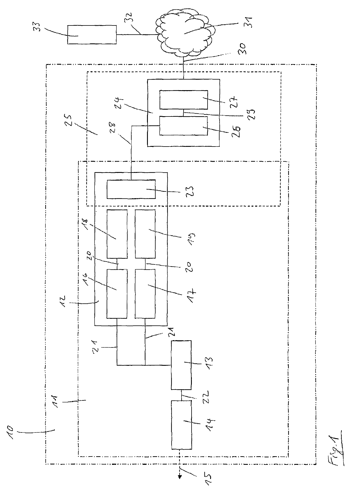
[0059]FIG. 1 shows a schematic illustration of a pump system 10. The pump system 10 comprises a pump unit 11 composed of a pump device 12 for pumping component material, a mixer 13 and a spray gun 14. By means of the spray gun 14, a multi-component material mixed from the component materials in the mixer 13 can be sprayed or ejected onto a surface, as is indicated here by arrow 15. The pump device 12 itself comprises a first pump 16 and another pump 17 and a first liquid tank 18 and another liquid tank 19, each for receiving liquid component material. The liquid tanks 18 and 19 are connected to the pumps 16 and 17, respectively, via media lines 20, the pumps 16 and 17 being connected to the mixer 13 via media lines 21 and the mixer 13 being connected to the spray gun 14 via yet another media line 22. The pumps 16 and 17 are realized as pneumatically driven reciprocating piston pumps, allowing the pumps 16 and 17 to suction component materials from the liquid tanks 18 and 19, respect...

second embodiment

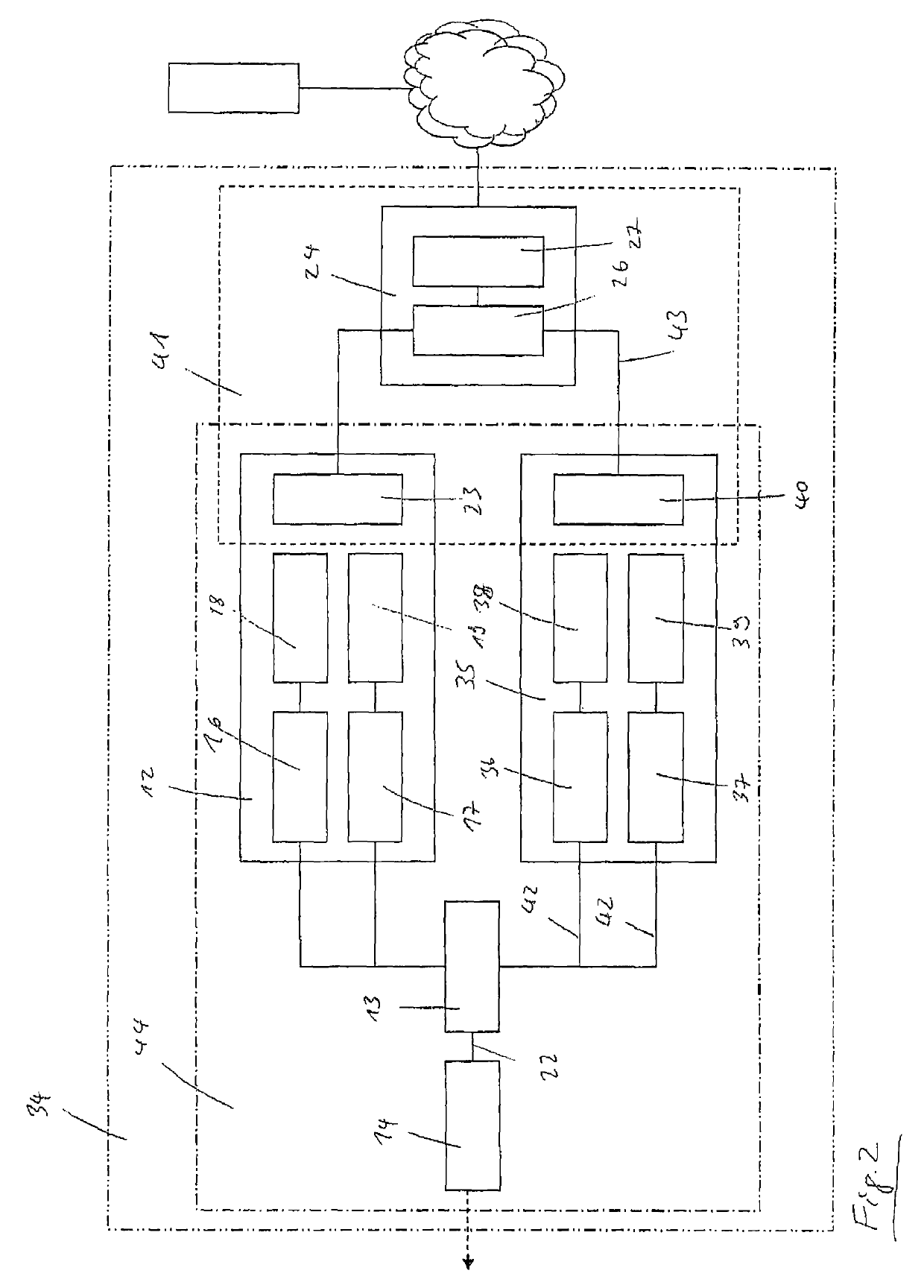
[0063]FIG. 2 shows a pump system 34, which differs from the pump system shown in FIG. 1 in that it has another pump device 35. The other pump device 35 is equipped with a first pump 36 and another pump 37, a first liquid tank 38 and another liquid tank 39 and an operating means 40. The operating means 23 and 40 now form a control unit 41 together with the control device 24. Also, the other pump device 35 is connected to the mixer 13 and to the spray gun 14 via media lines 42 and 22. Moreover, the control means 26 is wirelessly connected to the operating means 40 via a data connection 43. By means of the control device 24, it is now possible to simultaneously control pump device 12 and pump device 35 and to combine them with the mixer 13 and the spray gun 14 to form a pump unit 44. Pump device 12 and pump device 35 are substantially identical, allowing pump device 12 or 35 to be easily exchanged in case of failure of one of them without having to shut down the pump unit 44 entirely. ...

third embodiment

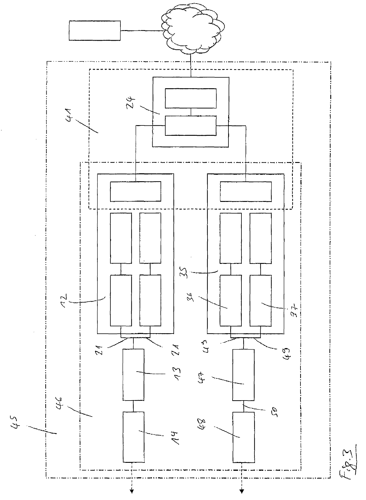
[0064]FIG. 3 shows a schematic illustration of a pump system 45. In contrast to the pump system illustrated in FIG. 2, a pump unit 46 is quipped with another mixer 47 and another spray gun 48 in this case, the first pump 36 and the other pump 37 being connected to the miser 47 via media lines 49 and the mixer 47 being connected to the spray gun 48 via a media line 50. The pump devices 12 and 35 can thus also be used while being completely separate from each other in terms of space, and the control device 24 can also be placed separately from the pump devices 12 and 35 in terms of location and space. Still, it is possible to control and monitor the pump devices 12 and 35 simultaneously.

[0065]FIG. 4 shows a schematic illustration of an operating means 51 together with a control device 52. The control device 52 is realized as a mobile phone 53 having a touch screen 54 and is coupled or connected with the operating means 51 via a radio data connection 55. The operating means 51 has a sc...


PUM


Abstract

The invention relates to a method for controlling a pump system and to a pump system (34) having a pump unit (44) for dispensing multi-component material under pressure by means of a spray gun, the pump unit comprising a pump device (12), a mixer (13) and a spray gun (14), the pump device having at least two pumps (16, 17) for pumping component material and associated liquid tanks (18, 19) for storing component material, the pump device having an operating means (23) by means of which the pump device is controlled, wherein the pump unit comprises at least one other pump device (35), the pump system having a control device (24), the control device and the operating means (23, 40) together forming a control unit (41), the pump unit being controlled by means of the control unit.

Description

FIELD OF THE INVENTION[0001]The invention relates to a method for controlling a pump system and to a pump system having a pump unit for dispensing multi-component material under pressure by means of a spray gun, the pump unit comprising a pump device, a mixer and a spray gun, the pump device having at least two pumps for pumping component material and associated liquid tanks for storing component material, the pump device having an operating means by means of which the pump device is controlled.BACKGROUND OF THE INVENTION[0002]Pump systems and methods of this kind for controlling and operating pump systems are well known from the state of the art and are regularly used for surface coating, i.e. to apply or spray multi-component material onto a surface. The multi-component material consists of one or more basic component materials and a hardener component material, each of these component materials being stored separately in liquid tanks. Each liquid tank is associated with a pump fo...

Claims


Application Information

Patent Timeline
Patent Type & Authority Patents(United States)
IPC IPC(8): F04B49/06F04B49/10F04B49/02F04B23/02F04B19/22B05B12/08B05B11/00B05B7/26F04B13/02F04B17/03F04B17/06
CPCB05B11/3001F04B49/02F04B49/06F04B49/065B05B7/26F04B17/03F04B13/02F04B23/02F04B17/06B05B12/08F04B19/22F04B49/10B05B11/1001
Inventor TURCZAK, PETER
Owner WIWA WILHELM WAGNER
Why Eureka
Try Eureka