Display panel

a display panel and gate driver technology, applied in the field of display panels, can solve the problems of failure to successfully dispose of the gate driver circuit in the display region, and achieve the effects of reducing cost, increasing display area, and reducing frame siz

Active Publication Date: 2019-09-24
AU OPTRONICS CORP
View PDF36 Cites 0 Cited by
  • Summary
  • Abstract
  • Description
  • Claims
  • Application Information

AI Technical Summary

Benefits of technology

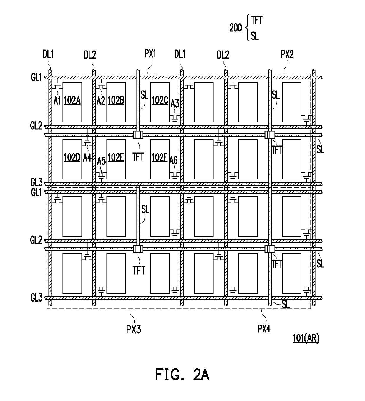
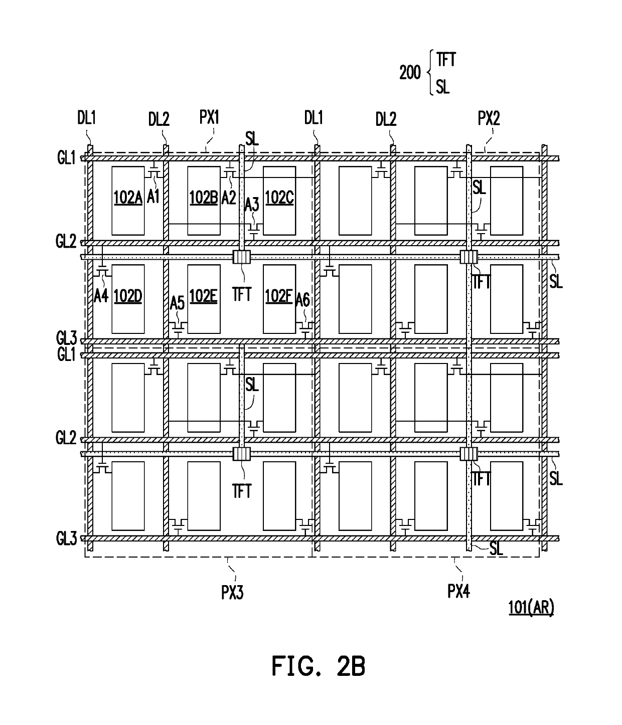
[0006]According to at least one embodiment of the disclosure, each of the pixel units of the display panel includes three gate lines, two data lines and six sub-pixels. In this manner, there is extra space for the gate driver circuit to be disposed in the pixel array of the display region. Accordingly, when the gate driver circuit is moved into the display region, it is possible to achieve the technical effect of reducing cost, significantly decreasing the frame and increasing the area of display region.

Problems solved by technology

However, conventionally the gate driver circuit occupies a large portion of the border area.
In ten is of known technologies, there is no successful attempt in disposing the gate driver circuit in the display region yet.

Method used


Image

  • Display panel
  • Display panel
  • Display panel

Examples


Embodiment Construction

[0023]In the drawings, in order show the illustrations clearly, the thickness of layers, films, panels and regions are exaggerated. Throughout the specification, the same reference numeral denotes the same element. It should be understood that when it is described that an element on the layer, film, region or substrate is “on” another element or “connected to” another element, it can be either directly on another element or connected to another element; alternatively, an intervening element may be present. On the contrary, when it is described that an element is “directly on another element” or “directly connected to” another element, no intervening element is present there. As described in the present text, “connected to” or “coupled to” may refer to physical and / or electrical connection. Alternatively, “electrically connected” or “coupled to” may refer to that there is another element existed between two elements.

[0024]Unless defined otherwise, all technical and scientific terms u...


PUM


Abstract

A display panel including a display region and a non-display region, a plurality of gate lines, a plurality of data lines, a pixel array and a gate on array circuit. The non-display region is located at one side of the display region. The plurality of gate lines and the plurality of data lines are disposed in the display region. The pixel array is located in the display region, wherein the pixel array is composed of a plurality of pixel units that are repeatedly arranged. The pixel units consist of three gate lines, two data lines and six sub-pixels, and each sub-pixel is electrically connected to one of the gate lines and one of the data lines located in the pixel array respectively. The gate on array circuit is disposed in the pixel array.

Description

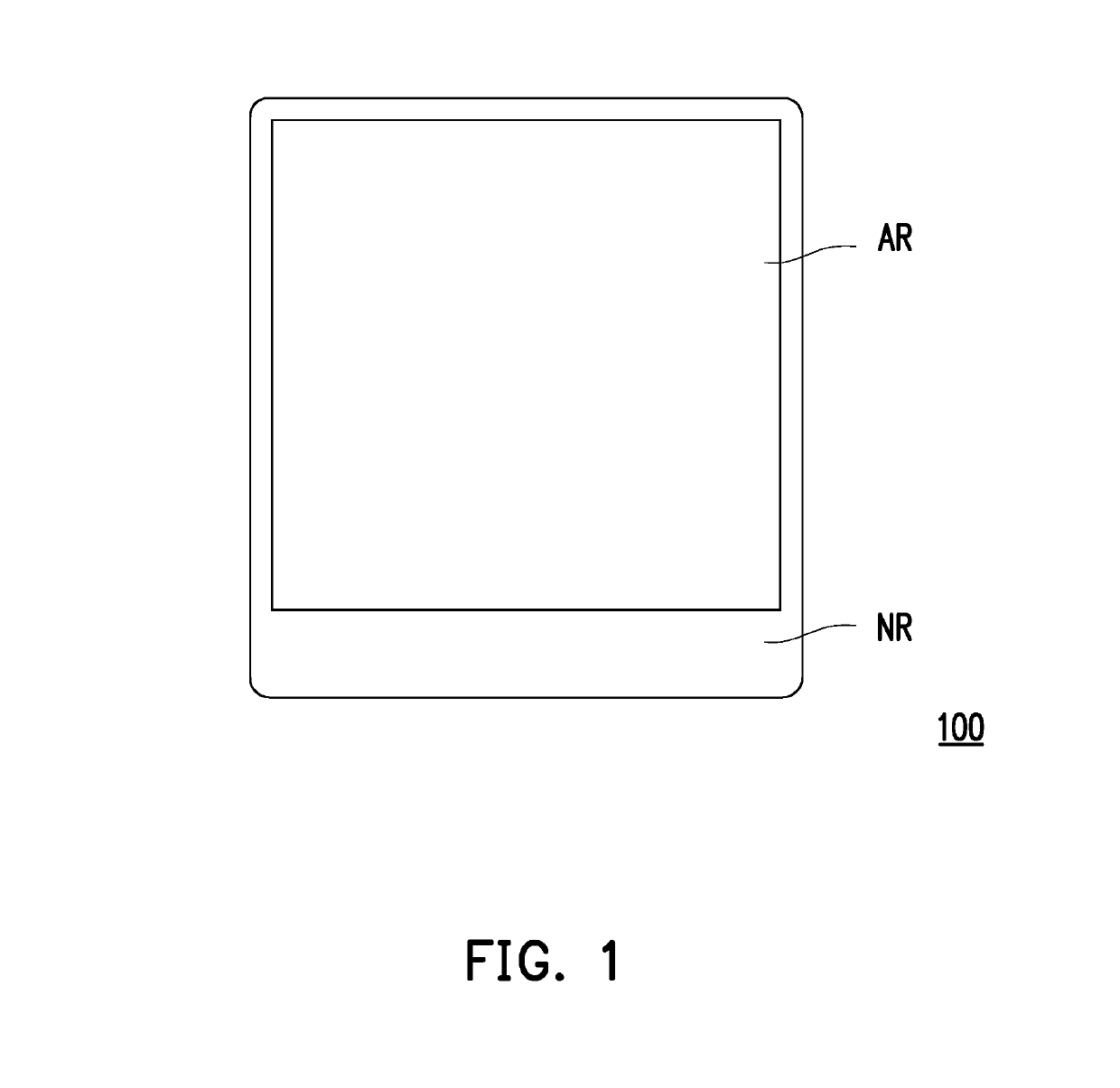
CROSS-REFERENCE TO RELATED APPLICATION[0001]This application claims the priority benefits of Taiwan application serial no. 106115682, filed on May 12, 2017, and Taiwan application serial no. 107101351, filed on Jan. 15, 2018. The entirety of each of the above-mentioned patent applications is hereby incorporated by reference herein and made a part of specification.BACKGROUNDField of the Disclosure[0002]The disclosure is related to a display panel, and particularly to a display panel in which a gate driver circuit is disposed in pixel array.Description of Related Art[0003]Gate on Array (GOA) circuit substrate technique refers to a technique through which a gate driver circuit is directly fabricated on an active element array substrate in design of panel to replace external driving chip. Typically, the gate driver circuit is disposed in the peripheral region nearby the display region of panel. However, conventionally the gate driver circuit occupies a large portion of the border area. ...

Claims


Application Information

Patent Timeline
Patent Type & Authority Patents(United States)
IPC IPC(8): H01L27/12G09G3/20G11C19/28
CPCG11C19/28H01L27/124H01L27/1255G09G3/20G09G2300/0408G09G2310/0286G09G3/2092G09G2300/0809
Inventor WANG, CHENG-KUANGTU, CHUN-DA
Owner AU OPTRONICS CORP
Why Eureka
Try Eureka