Method and device for detecting a neural response in a neural measurement

a neural response and neural measurement technology, applied in the field of neural response detection, can solve the problems of difficult task, presenting a significant obstacle to isolating or even detecting the much smaller cap signal of interest, and the impracticality of implant systems, so as to achieve the effect of better rejecting artifacts

Active Publication Date: 2019-10-01
SALUDA MEDICAL PTY LTD
View PDF311 Cites 29 Cited by
  • Summary
  • Abstract
  • Description
  • Claims
  • Application Information

AI Technical Summary

Benefits of technology

[0026]The present invention thus provides for selection of a filter template having improved artifact rejection. The present invention recognises that artifact can be reasonably accurately modelled as a sum of two exponentials having distinct time constants, and that because a Bartlett filter template window rejects the first three terms of a Taylor expansion of ex, namely the DC, linear, and quadratic terms, such embodiments of the present invention thus facilitate artifact rejection.
[0046]Some embodiments of the first through fourth aspects of the invention may provide a method for efficiently determining an optimum time delay when a signal to artifact ratio is greater than one, at which a first or single point of the cross-correlation between the neural measurement and the filter template should be produced, the method comprising:
[0051]Other embodiments of the third and fourth aspects of the invention may provide a method for efficiently determining an optimum time delay at which a first or single point of the cross-correlation between the neural measurement and the filter template should be produced, the method comprising:
[0060]While four lobes provides the optimal trade-off between rejection of artifact and noise gain, alternative embodiments of the present invention may usefully employ a filter template comprising greater or fewer lobes. In such embodiments the filter template may comprise one or more basis functions derived from a sinusoidal binomial transform (SBT), for example. In embodiments comprising a three or five lobed filter template the window preferably comprises a flat central portion, as returned by the SBT, rather than a triangular peak for example, in order to better reject DC and ramp components of a Taylor expansion and thus better reject artifact. Some embodiments of the invention may use multiple identical filter template elements, but shifted in time. Even though these are not orthogonal, a successive approximation method creating a compound template may provide better approximation. Additionally or alternatively, some embodiments may use templates that are a sum of templates of different frequencies, templates of different offset and / or templates of different numbers of lobes.

Problems solved by technology

However, this can be a difficult task as an observed CAP signal component in the neural measurement will typically have a maximum amplitude in the range of microvolts.
In contrast a stimulus applied to evoke the CAP is typically several volts and results in electrode artifact, which manifests in the neural measurement as a decaying output of several millivolts partly or wholly contemporaneously with the CAP signal, presenting a significant obstacle to isolating or even detecting the much smaller CAP signal of interest.
For example, to resolve a 10 μV CAP with 1 μV resolution in the presence of an input 5V stimulus, for example, requires an amplifier with a dynamic range of 134 dB, which is impractical in implant systems.
As the neural response can be contemporaneous with the stimulus and / or the stimulus artifact, CAP measurements present a difficult challenge of measurement amplifier design.
In practice, many non-ideal aspects of a circuit lead to artifact, and as these mostly have a decaying exponential appearance that can be of positive or negative polarity, their identification and elimination can be laborious.
The difficulty of this problem is further exacerbated when attempting to implement CAP detection in an implanted device.

Method used


Image

  • Method and device for detecting a neural response in a neural measurement
  • Method and device for detecting a neural response in a neural measurement
  • Method and device for detecting a neural response in a neural measurement

Examples


Embodiment Construction

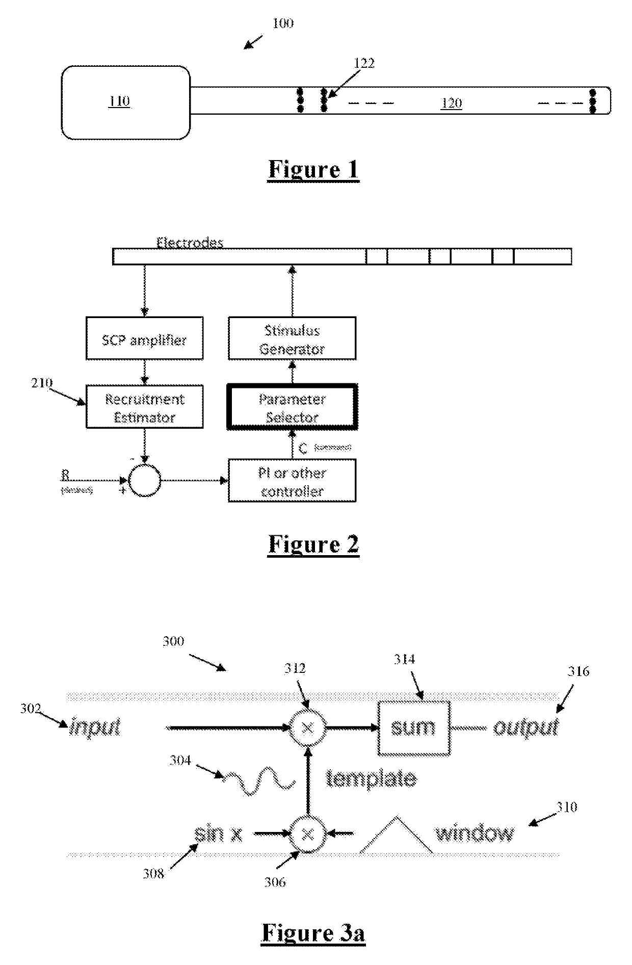
[0078]FIG. 1 illustrates an implantable device 100 suitable for implementing the present invention. Device 100 comprises an implanted control unit 110, which controls application of neural stimuli, and controls a measurement process for obtaining a measurement of a neural response evoked by the stimuli from each of a plurality of electrodes. The control unit 110 includes a storage memory (or other storage device(s), not shown) for storing a lookup table that contains data defining a therapy map, setting out a relationship between applied stimuli regimes and the desired neural response. Device 100 further comprises an electrode array 120 consisting of a three by eight array of electrodes 122, each of which may be selectively used as either the stimulus electrode or sense electrode, or both.

[0079]FIG. 2 is a schematic of a feedback controller implemented by the control unit 110, based on recruitment. An important component of such feedback control is a recruitment estimator 210, which...


PUM


Abstract

A method for processing a neural measurement obtained in the presence of artifact, in order to detect whether a neural response is present in the neural measurement. A neural measurement is obtained from one or more sense electrodes. The neural measurement is correlated against a filter template, the filter template comprising at least three half cycles of an alternating waveform, amplitude modulated by a window. From an output of the correlating, it is determined whether a neural response is present in the neural measurement.

Description

CROSS-REFERENCE TO RELATED APPLICATIONS[0001]This application is a national stage of Application No. PCT / AU2014 / 050369 filed Nov. 22, 2014, which application claims the benefit of Australian Provisional Patent Application No. 2013904519 filed Nov. 22, 2013, the disclosures of which are incorporated herein by reference in their entirety.TECHNICAL FIELD[0002]The present invention relates to detection of a neural response, such as a neural response caused by a stimulus. In particular the present invention relates to detection of a compound action potential by using one or more electrodes implanted proximal to the neural pathway to obtain a neural measurement.BACKGROUND OF THE INVENTION[0003]Electrical neuromodulation is used or envisaged for use to treat a variety of disorders including chronic pain, Parkinson's disease, and migraine, and to restore function such as hearing and motor function. A neuromodulation system applies an electrical pulse to neural tissue in order to generate a ...

Claims


Application Information

Patent Timeline
Patent Type & Authority Patents(United States)
IPC IPC(8): A61B5/00A61B5/04G06K9/00A61N1/36
CPCG06K9/00496A61B5/04001A61B5/7282A61N1/36071A61B5/6846A61B5/7246A61N1/36139A61B5/7203A61B2562/046A61B5/6877A61B5/4848A61B5/7257A61B5/24G06F2218/00
Inventor SINGLE, PETER SCOTT VALLACK
Owner SALUDA MEDICAL PTY LTD
Why Eureka
Try Eureka