

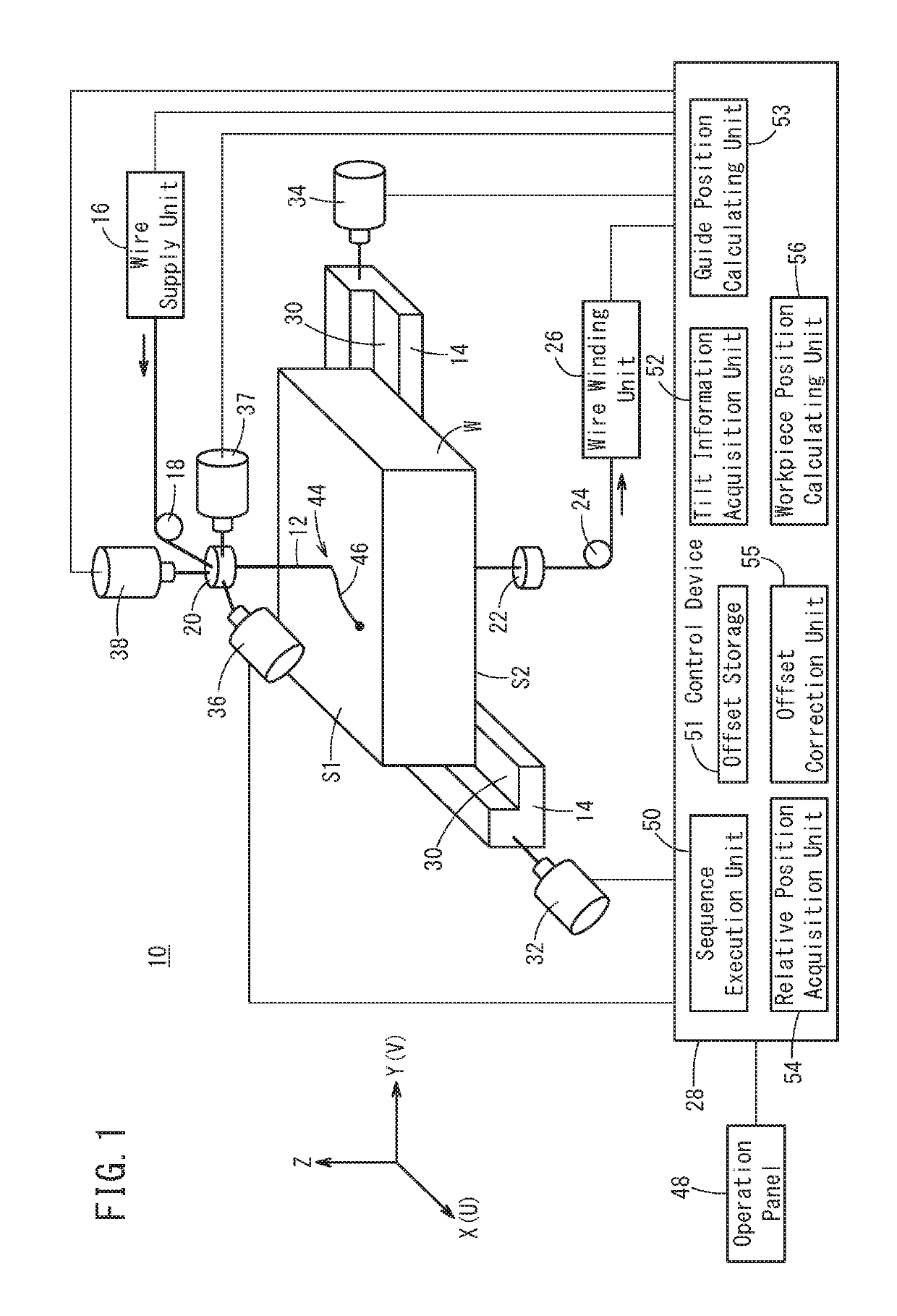
Wire electrical discharge machine and wire electrical discharge machining method
a wire electrical discharge and wire electrical discharge technology, applied in the direction of computer control, program control, instruments, etc., can solve the problem of inability to obtain desired measurement results, and achieve the effect of maintaining processing accuracy
- Summary
- Abstract
- Description
- Claims
- Application Information
AI Technical Summary
Benefits of technology
Problems solved by technology
Method used
Image

Examples
example 3
Calculation Example 3
[0083]As a third calculation example, a method of acquiring a Z-axis relative position from the lower guide portion 66 to the probe 64 will be described. Specifically, this can be calculated by subtracting [2] the Z-axis relative position from the upper guide portion 60 to the lower guide portion 66, from [1] the Z-axis relative position from the upper guide portion 60 to the probe 64.
[0084]In this way, the relative position acquisition unit 54 acquires the Z-axis relative positions between the upper guide portion 60, the lower guide portion 66, and the probe 64 (Step S4). It should be noted that the relative position acquisition unit 54 may acquire the Z-axis relative position after correcting the Z-coordinate based on the size of the sensor part 70 provided for the probe 64.
5)>
[0085]At Step S5 in FIG. 4, the control device 28 (offset correction unit 55) corrects the offset measured at Step S1 using the information obtained from Steps S2 to S4. That is, the off...
example 1
Calculation Example 1
[0086]In the first calculation example, the offset correction unit 55 calculates a correction amount of the offset from the relationship between the Z-axis relative position from the upper guide portion 60 to the probe 64 and the tilt angle θ of the workpiece W.
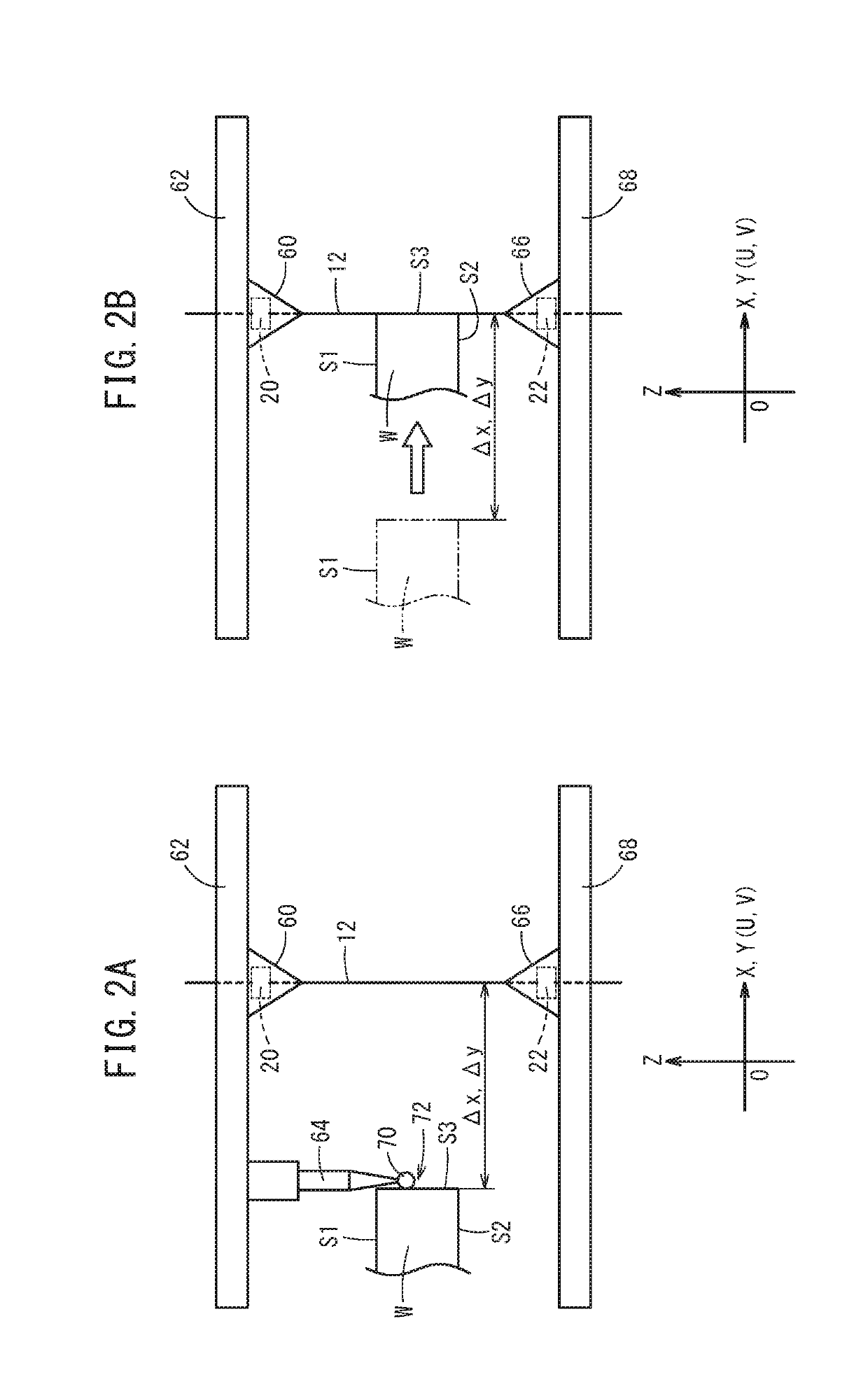
[0087]FIG. 10 is a schematic view for explaining the first example of calculation by the offset correction unit 55. A point A indicates the position of the upper guide portion 60. A point B indicates the position of the lower guide portion 66 after movement. A point C indicates the position of the lower guide portion 66 before movement. A point D is a point of intersection between a line segment AB and a line that passes through the position (point P) of the probe 64 and is parallel to the XY-plane. A point E is a point of intersection between a line segment AC and a line that passes through a point P and is parallel to the XY-plane.
[0088]By simple geometrical considerations, a vector DE↑ is given by the ...
example 2
Calculation Example 2
[0090]In the second calculation example, the offset correction unit 55 calculates a correction amount of the offset based on the amount of movement of the lower guide portion 66 and the relation of at least two Z-axis relative positions.
[0091]FIG. 11 is a schematic diagram for explaining a second calculation example by the offset correction unit 55. The definitions of the points A to E are the same as those in FIG. 10 and will not be described.
[0092]By simple geometrical considerations, the vector DE↑ is given by the following equation (4). Here, BC↑ is an inverse vector of the movement of the lower guide portion 66. Further, the magnitude of |AE| is calculated at Step S4 (first calculation example), and the magnitude of |AC| is calculated at Step S4 (second calculation example).
DE↑=|AE| / |AC|·BC↑ (4)
[0093]Alternatively, the vector DE↑ is expressed by the following equations (5) and (6) in place of Eq. (4). Here, the magnitude of |EC| is calculated at Step S4 (t...
PUM
| Property | Measurement | Unit |
|---|---|---|
| tilt angle | aaaaa | aaaaa |
| size | aaaaa | aaaaa |
| adhesion | aaaaa | aaaaa |
Abstract
Description
Claims
Application Information