Machine tool and cutting method

a cutting method and machine tool technology, applied in the direction of turning apparatus, metal-working equipment, turning machine accessories, etc., can solve the problems of deformation of workpiece or cutting tool, and deviation of machining dimension from design value, so as to reduce the moving distance of cutting tools, maintain machining accuracy, and reduce the effect of machining tim

Inactive Publication Date: 2018-04-26
MURATA MASCH LTD
View PDF30 Cites 1 Cited by
  • Summary
  • Abstract
  • Description
  • Claims
  • Application Information

AI Technical Summary

Benefits of technology

[0005]Preferred embodiments of the present invention provide machine tools and cutting methods that are able to machine workpieces with high accuracy and to reduce the machining time.
[0010]According to the machine tools of preferred embodiments of the present invention, the multiple cutting tools are held by the holder. Thus, when multiple cutting steps are performed on the workpiece W, for example, when main machining (rough machining) and finish machining are performed thereon, the moving distance of the cutting tools is reduced. As a result, it is possible to reduce the machining time while maintaining the machining accuracy. Also, the linear cutting blades are not parallel with each other. Thus, by setting machining using the front cutting tool and machining using the rear cutting tool to angles suitable for the respective types of machining, it is possible to machine the workpieces with high accuracy so that the roughness of the cutting surface is improved.
[0011]If the holder holds the cutting tools in such a manner that the angle with respect to the Z-direction, of the linear cutting blade of the cutting tool disposed in front in the moving direction, of the cutting tools becomes greater than the angle with respect to the Z-direction, of the linear cutting blade of the cutting tool disposed in the rear in the moving direction, thereof, it is possible to perform main machining (rough machining) using the front cutting tool and to perform finish machining using the rear cutting tool so that the surface roughness is reduced. If the moving direction is the Y-direction, or the direction obtained by combining the Z-direction and the Y-direction, the workpiece is able to be cut using the multiple cutting tools by only moving the holder once. If the holder is moved in the direction obtained by combining the Z-direction and the Y-direction, the region which is wide in the Z-direction, of the workpiece is cut. Thus, the moving distance of the holder is reduced, allowing the machining time to be reduced. If the holder holds the cutting tools in such a manner that the positions of the linear cutting blades are the same in the X-direction, the tools are disposed in such a manner that the amounts of the workpiece to be cut by the tools are equalized. Thus, a cutting error made by the front linear cutting blade is able to be corrected by the rear linear cutting blade. That is, the workpiece is able to be machined with high accuracy. If the holder holds the cutting tools in such a manner that the linear cutting blade of the cutting tool disposed in the rear in the moving direction, of the cutting tools protrudes in the X-direction toward the workpiece compared to the linear cutting blade of the cutting tool disposed in front in the moving direction, thereof, multiple cutting steps are able to be performed on the workpiece with high accuracy in a short time. If the front end of the rear linear cutting blade and the rear end of the front linear cutting blade are spaced from each other in the Y-direction, the workpiece is cut using the rear cutting tool after the front cutting tool leaves the workpiece. Thus, it is possible to eliminate the flexure or the like of the workpiece caused by the front cutting tool when cutting the workpiece using the rear cutting tool and to cut the workpiece with high accuracy using the rear cutting tool. If the linear cutting blades of the cutting tools have the same lengths perpendicular or substantially perpendicular to the moving direction, the cutting ranges of the workpiece are equalized. Thus, the ranges cut using the cutting tools are made the same.
[0012]According to the cutting methods of preferred embodiments of the present invention, with the multiple cutting tools disposed, the workpiece is cut using the front cutting tool and then cut using the rear cutting tool. Thus, multiple cutting steps such as main machining (rough machining) and finish machining are able to be performed on the workpiece with high accuracy in a short time. Also, the linear cutting blades are not parallel with each other. Thus, by setting machining using the front cutting tool and machining using the rear cutting tool to angles suitable for the respective types of machining, it is possible to machine the workpiece with high accuracy so that the roughness of the cutting surface is improved.
[0013]If main machining is performed on the workpiece using the cutting tool disposed in front in the moving direction and finish machining is performed on the workpiece using the cutting tool disposed in the rear in the moving direction, multiple cutting steps such as main machining (rough machining) and finish machining are able to be performed on the workpiece. If, in case that the moving direction is the direction obtained by combining the Z-direction and the Y-direction, the cutting method includes adjusting the angles with respect to the Z-direction, of the linear cutting blades disposed in front and in the rear in the moving direction on the basis of the amount of movement in the Z-direction prior to cutting the workpiece, the workpiece is able to be cut with high accuracy by adjusting the front and rear linear cutting blades to angles suitable for the respective types of machining.

Problems solved by technology

If the machining method disclosed in Japanese Patent No. 3984052 is used, the workpiece or cutting tool may be deformed during cutting, and the machining dimension may deviate from the design value.
Thus, the deformation of the workpiece or cutting tool may be increased, and the machining dimension may significantly deviate from the predetermined value.
This disadvantageously increases the distance traveled by the cutting tool and increases the machining time.

Method used


Image

  • Machine tool and cutting method
  • Machine tool and cutting method
  • Machine tool and cutting method

Examples


first preferred embodiment

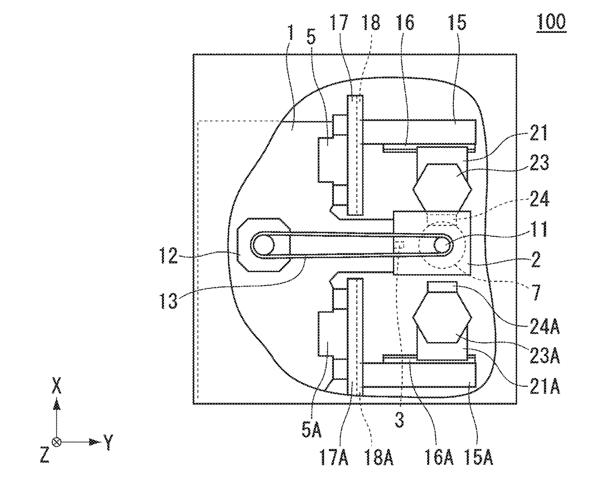
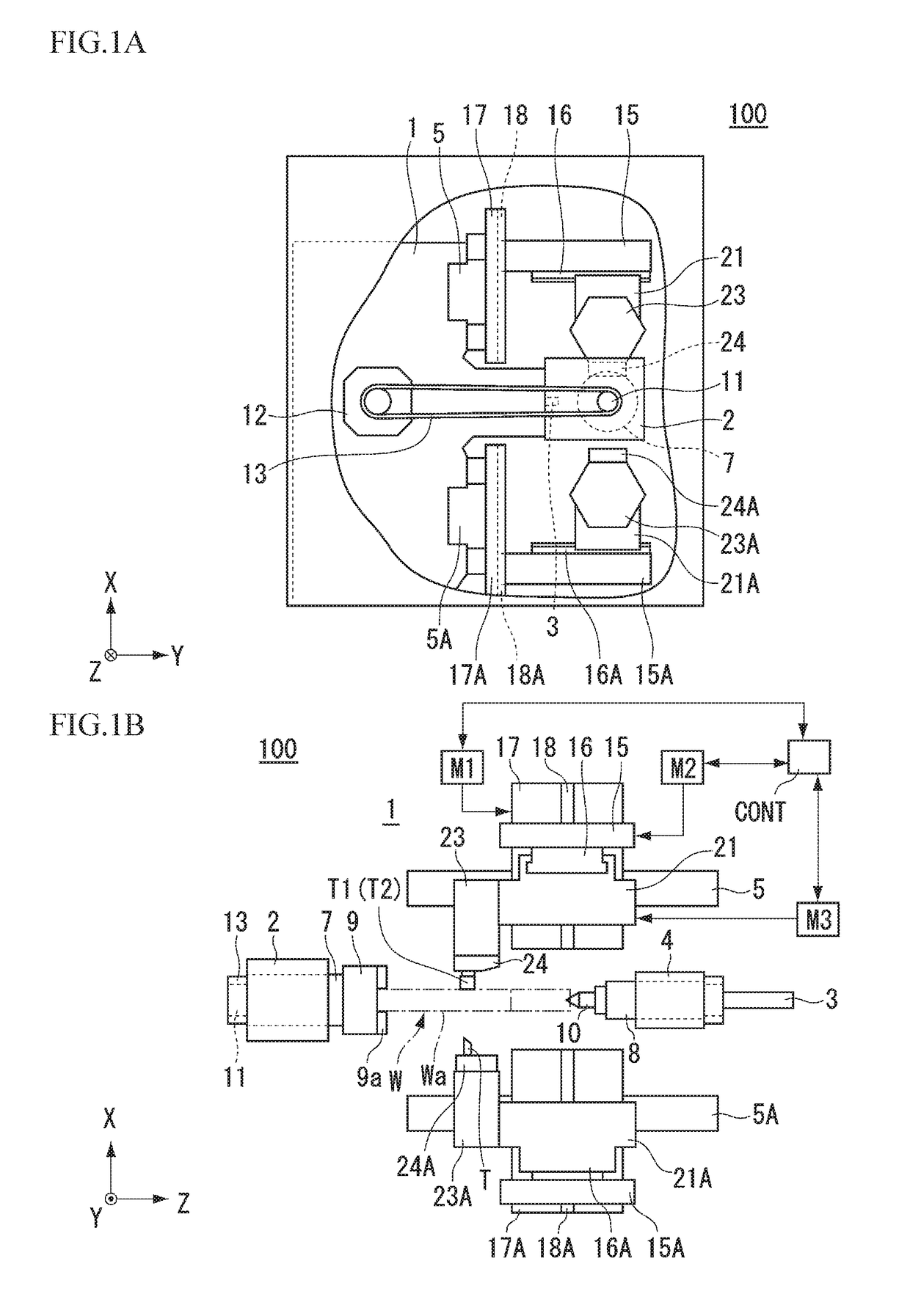
[0030]A machine tool 100 of a first preferred embodiment will be described with reference to the drawings. FIGS. 1A and 1B include drawings showing an example of a major portion of the machine tool 100 of the first preferred embodiment, in which FIG. 1A is a side view; and FIG. 1B is a front view. The machine tool 100 shown in FIGS. 1A and 1B is a lathe. In FIGS. 1A and 1B, the front side of the machine tool 100 is located on the positive Y-side, and the back side thereof is located on the negative Y-side. The lateral sides of the machine tool 100 are located on the positive and negative Z-sides, and the Z-direction represents the left-right direction of the machine tool 100.

[0031]As shown in FIGS. 1A and 1B, the machine tool 100 includes a base 1. The base 1 is provided with a headstock 2 and a tailstock 4. The headstock 2 rotatably supports a main spindle 7 with a bearing or the like (not shown) therebetween. While the headstock 2 is fixed to the base 1, it may be movable in the Z...

second preferred embodiment

[0071]A machine tool 200 of a second preferred embodiment of the present invention will be described. FIG. 10 shows an example of a tool head 124 of the machine tool 200 of the second preferred embodiment seen in the positive X-direction. Elements not shown in FIG. 10 are similar to those of the machine tool 100 described in the first preferred embodiment. Also, elements identical or similar to those in the first preferred embodiment in FIG. 10 are given the same reference signs, and the description thereof will be omitted or simplified. Note that in FIG. 10, an insertion member 26 or bolt 27 as shown in FIGS. 3A and 3B is not shown. In the second preferred embodiment, the position of a second cutting tool T2 with respect to a first cutting tool T1 differs from that in the first preferred embodiment.

[0072]In the first preferred embodiment, the configuration in which the first cutting tool T1 and the second cutting tool T2 are disposed in positions aligned with each other in the Y-di...

third preferred embodiment

[0080]A machine tool 300 of a third preferred embodiment of the present invention will be described. FIG. 12 shows an example of a holder 225 of the machine tool 300 of the third preferred embodiment seen in the positive X-direction. Elements not shown in FIG. 12 are similar to those of the machine tool 100 described in the first preferred embodiment. Also, elements identical or similar to those in the first preferred embodiment in FIG. 12 are given the same reference signs, and the description thereof will be omitted or simplified. In the third preferred embodiment, the position of a second cutting tool T2 with respect to a first cutting tool T1 differs from that in the first preferred embodiment.

[0081]In the first preferred embodiment, the configuration in which the first cutting tool T1 and the second cutting tool T2 are inclined in the same direction with respect to the Z-direction has been described as an example. In the third preferred embodiment, on the other hand, the second...


PUM

PropertyMeasurementUnit
angleaaaaaaaaaa
lengthsaaaaaaaaaa
cutting forceaaaaaaaaaa

Abstract

A machine tool includes a main spindle that rotates while holding a workpiece, a holder that holds first and second cutting tools including first and second linear cutting blades to cut the workpiece, and a moving device that moves the first and second cutting tools relative to the workpiece in a moving direction including at least a Z-direction and a Y-direction. The holder holds the first and second cutting tools such that the cutting tools are arranged along the moving direction in a state in which the directions of the linear cutting blades are inclined with respect to the Z-direction when seen from the X-direction and are not parallel with each other.

Description

BACKGROUND OF THE INVENTION1. Field of the Invention[0001]The present invention relates to a machine tool and a cutting method.2. Description of the Related Art[0002]A lathe, which is one type of machine tool, holds a workpiece to be machined, on the rotating shaft (spindle) and performs cutting or the like on the workpiece using a cutting tool while rotating the workpiece. As a machining method using a lathe, for example, there is known a method of cutting a workpiece while feeding a cutting tool in a tangential direction of the workpiece (a direction crossing the rotating shaft) (for example, see Japanese Patent No. 3984052).[0003]If the machining method disclosed in Japanese Patent No. 3984052 is used, the workpiece or cutting tool may be deformed during cutting, and the machining dimension may deviate from the design value. In particular, if the workpiece is cut by a large amount, the cutting force is increased. Thus, the deformation of the workpiece or cutting tool may be incre...

Claims


Application Information

Patent Timeline
Patent Type & Authority Applications(United States)
IPC IPC(8): B23B1/00B23B27/02
CPCB23B1/00B23B27/02B23B2210/02
Inventor ISHIHARA, TADASHI
Owner MURATA MASCH LTD
Why Eureka
Try Eureka