
Image processing apparatus, learning appratus, image processing method, learning method and program

a learning device and image processing technology, applied in the field of image processing apparatus, can solve the problems of large degraded image processing accuracy, difficult to automate all visual inspection processes in various businesses using an image processing system, and inability to easily restore original images from feature quantities, etc., to achieve the effect of maintaining image processing accuracy and reducing code amounts

Active Publication Date: 2022-03-24
NIPPON TELEGRAPH & TELEPHONE CORP
View PDF0 Cites 1 Cited by
  • Summary
  • Abstract
  • Description
  • Claims
  • Application Information

AI Technical Summary

Benefits of technology

The invention helps reduce the amount of code needed while maintaining image processing accuracy.

Problems solved by technology

The latter type of scheme is efficient in terms of power consumption or calculation time, but does not easily restore an original image from a feature quantity, for example, particularly when a hierarchy of the neural network that extracts the feature map is deep (See Non Patent Literature 1).
Further, it is difficult to automate all visual inspection processes in various businesses using an image processing system.
Further, Non Patent Literature 2 shows that, when a perturbation that humans can hardly distinguish is imparted to an image, the processing accuracy of image processing in a convolutional neural network may be greatly degraded.
That is, it can be said that the signal maintaining the image quality and the signal maintaining the image processing accuracy do not always match.
Considering these points, it can be said that the general image encoding scheme is insufficient as a scheme for maintaining the image processing accuracy.
Thus, it can be said that significant reduction in coding efficiency cannot be expected.
Thus, it is difficult for the technology described in Non Patent Literature 4 to be applied to an encoding system that does not include an adaptive quantization mechanism.
However, because it is assumed that a total code amount will increase due to an increase in calculation amount and an increase in a size of the header when the quantization table is assigned to each encoded block, it can be said that it is not realistic to introduce the adaptive quantization mechanism into JPEG.
However, the image encoding scheme described in Non Patent Literature 5 is based on characteristics of human perception and is not a scheme considering image processing accuracy.

Method used


Image

  • Image processing apparatus, learning appratus, image processing method, learning method and program
  • Image processing apparatus, learning appratus, image processing method, learning method and program
  • Image processing apparatus, learning appratus, image processing method, learning method and program

Examples


first embodiment

[0045]Hereinafter, a first embodiment of the present invention will be described with reference to the drawings.

[0046]Configuration of Image Processing Device

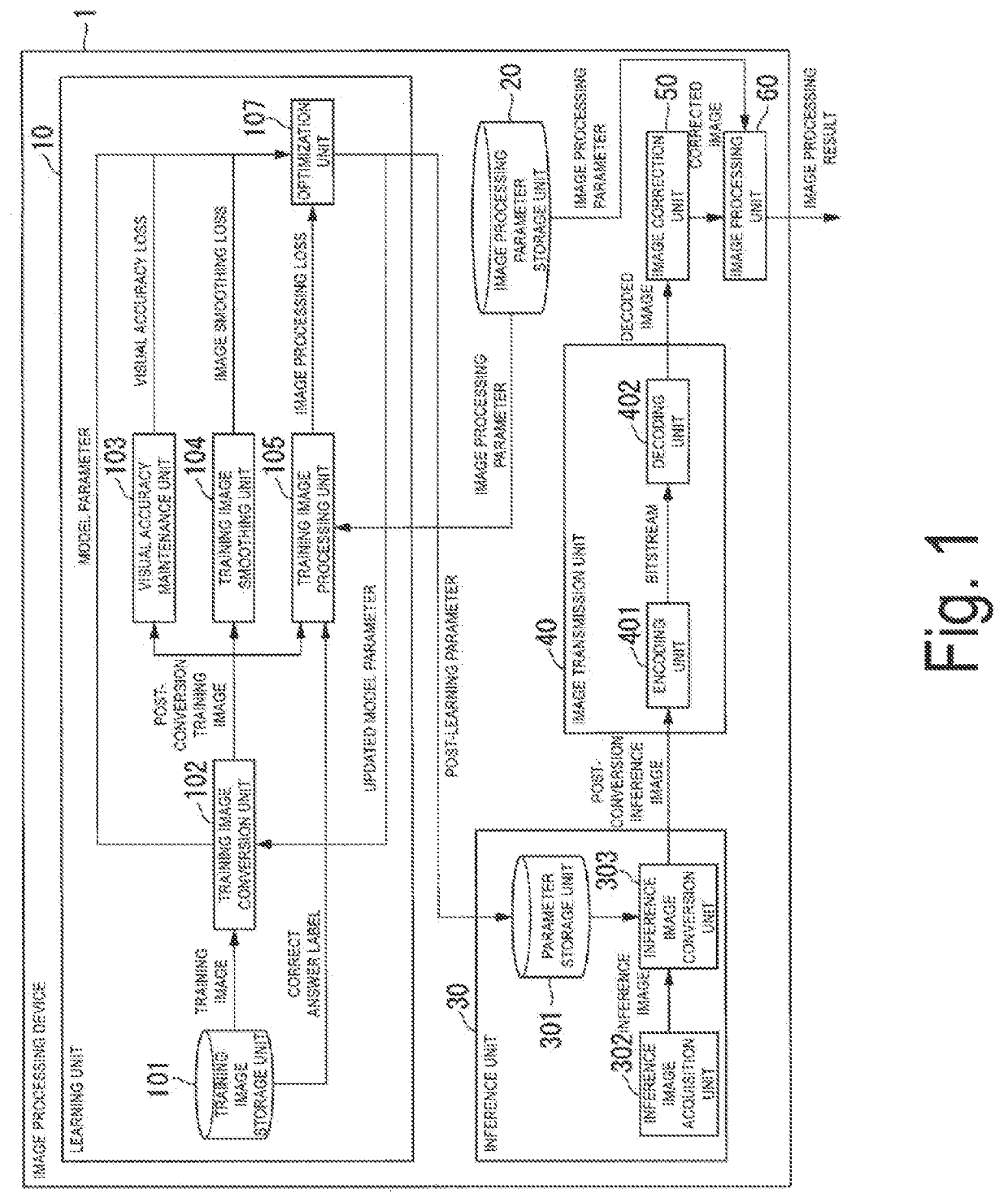
[0047]Hereinafter, a functional configuration of an image processing device 1 will be described. FIG. 1 is a block diagram illustrating a functional configuration of an image processing device 1 according to a first embodiment of the present invention. As illustrated in FIG. 1, the image processing device 1 includes a learning unit 10, an image processing parameter storage unit 20, an inference unit 30, an image transmission unit 40, an image correction unit 50, and an image processing unit 60.

[0048]A trained model subjected to machine learning (hereinafter referred to as “learning”) by the learning unit 10 is used by the inference unit 30 in a subsequent stage. Thus, there is a time difference between a timing at which the learning unit 10 performs a process and a timing at which functional units subsequent to the inference un...

second embodiment

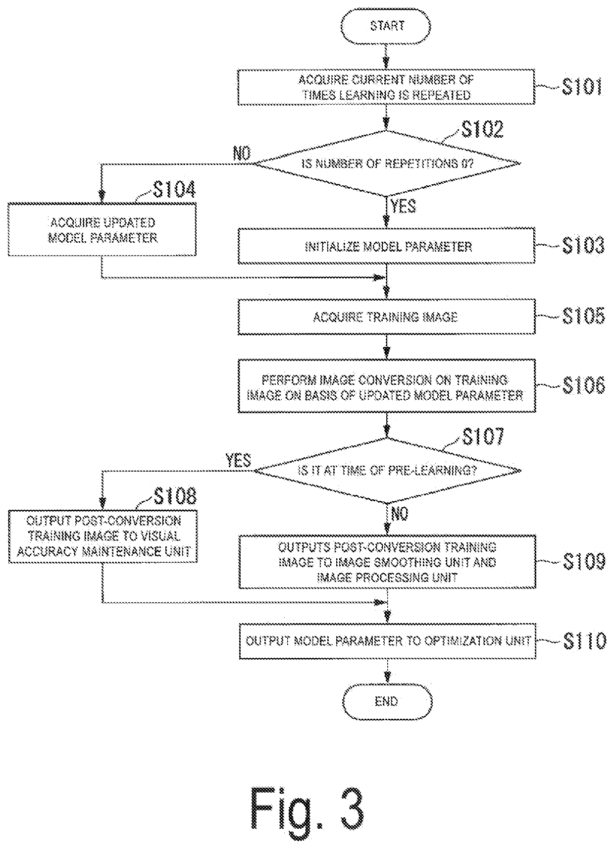
[0149]Several schemes can be considered for a learning process in the learning unit. These schemes are roughly divided into two schemes including a scheme for performing learning in which a process of the training image processing unit (hereinafter referred to as an “image processing model”) is not included in a learning target, and a scheme for performing learning in which the image processing model is included in the learning target The first embodiment described above is an example of the former type of scheme in which the image processing model is not included in the learning target.

[0150]On the other hand, in the latter type of scheme in which the image processing model is included in the learning target, the number of parameters to be learned increases as compared with the former type of scheme. Thus, a time required for learning becomes long and the number of pieces of data necessary for convergence of learning increases. However, the latter type of scheme has an advantage th...

third embodiment

[0174]Several methods can be considered for the learning process in the optimization unit included in the learning unit.

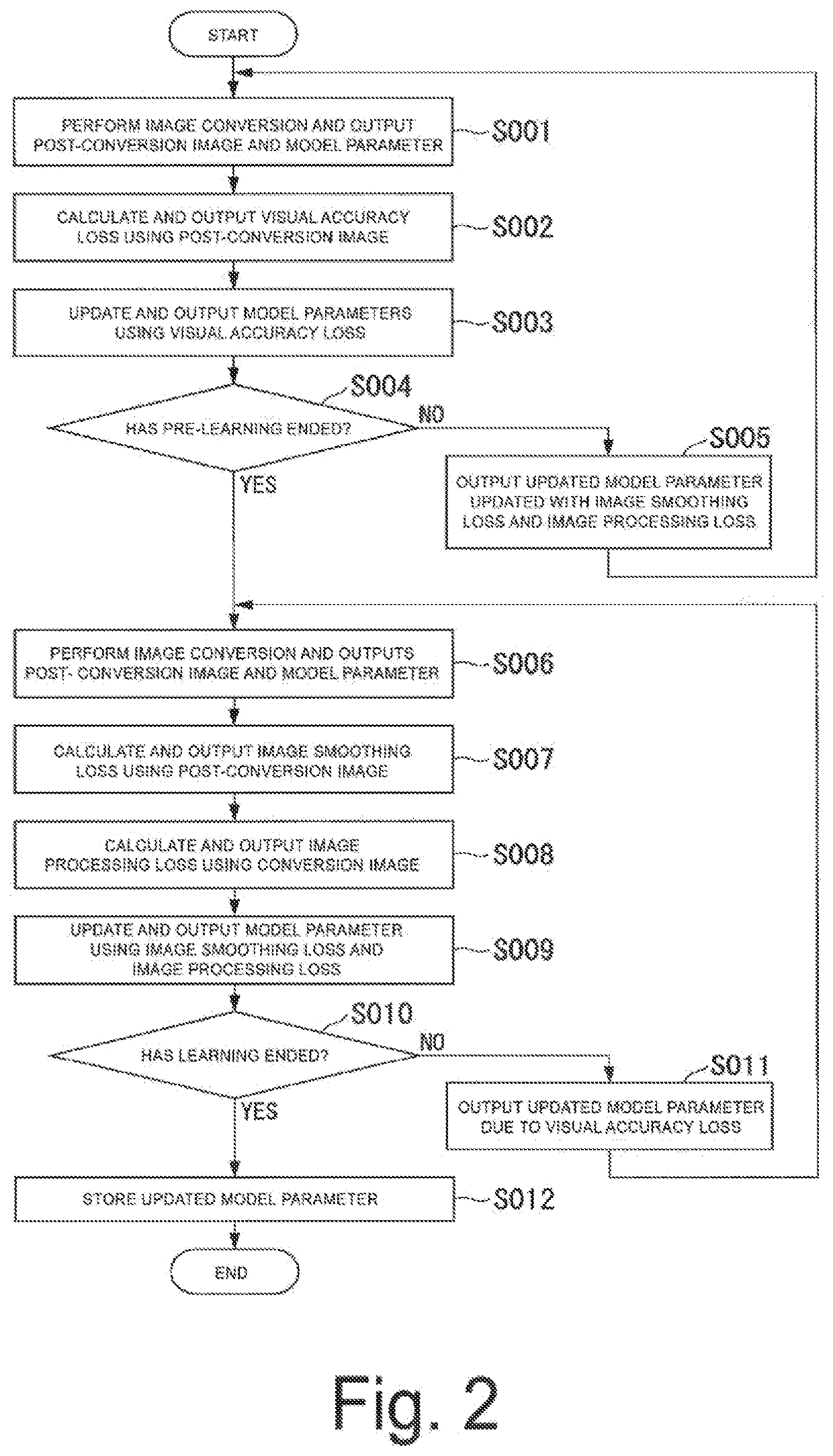
[0175]For example, the first embodiment shows the scheme in which the learning for the visual accuracy loss is treated as pre-learning of the image smoothing loss and the image processing loss, as described above.

[0176]On the other hand, a third embodiment shows a scheme in which the visual accuracy loss, the image smoothing loss, and the image processing loss are all learned at the same time. The latter type of scheme in which all of the three losses are learned at the same time has an advantage that, because all the losses can be learned at the same time, it is possible to further reduce the number of times learning has been repeated, as compared to the former type of scheme. The scheme of the third embodiment to be described below is a scheme that can be applied in a case in which the visual accuracy loss and the image processing loss are contradictory (for exam...


PUM


Abstract

An image processing device includes an image processing unit configured to execute image processing on an image based on an input image and output a result of the image processing, the input image is a post-conversion image obtained by performing image conversion on an original image, and the conversion includes image conversion for further decreasing a data size of the original image while maintaining a feature quantity used in the image processing and processing accuracy of the image processing.

Description

TECHNICAL FIELD[0001]The present invention relates to an image processing device, a learning device, an image processing method, a learning method, and a program.BACKGROUND ART[0002]In recent years, for example, the processing accuracy of image processing using machine learning for detection or identification of a subject in an image, division of the image into regions, and the like has improved remarkably. An image processing technology using such machine learning has been attracting attention as a technology for automating visual inspection processes in various businesses. In such image processing, for example, when an imaging device for capturing a processing target image is present in an environment in which the imaging device communicates with an edge server in a communication network and a server responsible for automation of a visual inspection process is present in a cloud environment that is present at a position physically remote from the imaging device, the captured image...

Claims


Application Information

Patent Timeline
IPC IPC(8): H04N19/154H04N19/136H04N19/85
CPCH04N19/154H04N19/85H04N19/136H04N19/80H04N1/41G06T7/00G06N3/084
Inventor SUZUKI, SATOSHITAKAGI, MOTOHIROHAYASE, KAZUYASHIMIZU, ATSUSHI
Owner NIPPON TELEGRAPH & TELEPHONE CORP
Learn More