Method and system for controlling a vehicle propulsion system

a technology of vehicle propulsion and control system, which is applied in fluid gearings, transportation and packaging, gearings, etc., can solve the problems of engine operating at a low speed, power that is required to increase the flow of the cvt hydraulic control pump, and the inability of the cvt to quickly reduce the ratio (as in a power downshift) to achieve the effect of increasing the acceleration of the vehicle incorporating the vehicle propulsion system, high fuel efficiency, and improving structur

Active Publication Date: 2019-10-01
GM GLOBAL TECH OPERATIONS LLC
View PDF3 Cites 0 Cited by
  • Summary
  • Abstract
  • Description
  • Claims
  • Application Information

AI Technical Summary

Benefits of technology

[0019]In this manner, the quickness with which a vehicle propulsion system which includes a continuously variable transmission, may implement a downshift is greatly increased, the acceleration of a vehicle incorporating the vehicle propulsion system is increased during a downshift, the ability to incorporate highly fuel efficient engine operating modes and CVT hydraulic pump operation, structure and size is improved without adversely affecting a downshift event, the responsiveness of the vehicle propulsion system to accelerate in response to a driver input is improved. This additionally improves the driver experience because the vehicle propulsion system may noticeably react more quickly to the driver input and may also result in smoother, improved shifting.

Problems solved by technology

In a coasting situation, this may result in the engine operating at a low speed.
However, this may result in challenges when additional power is requested by the driver.
However, the ability for the CVT to quickly reduce the ratio (as in a power downshift) may be reduced because the engine that provides the power to operate the CVT hydraulic control pump and to propel the vehicle may have started from a low engine speed and the power that is required to increase the flow to the CVT hydraulic control pump may not be immediately available.
This combination of factors may result in a delayed response to a driver request for increased torque.
Further, this problem may be further exasperated when the vehicle propulsion system is operated at higher altitudes.
This reduction in available power from the engine and, thus a reduced ability to quickly provide a ratio decrease, may further increase a delay in response to a driver request for increased torque.

Method used


Image

  • Method and system for controlling a vehicle propulsion system
  • Method and system for controlling a vehicle propulsion system
  • Method and system for controlling a vehicle propulsion system

Examples


Embodiment Construction

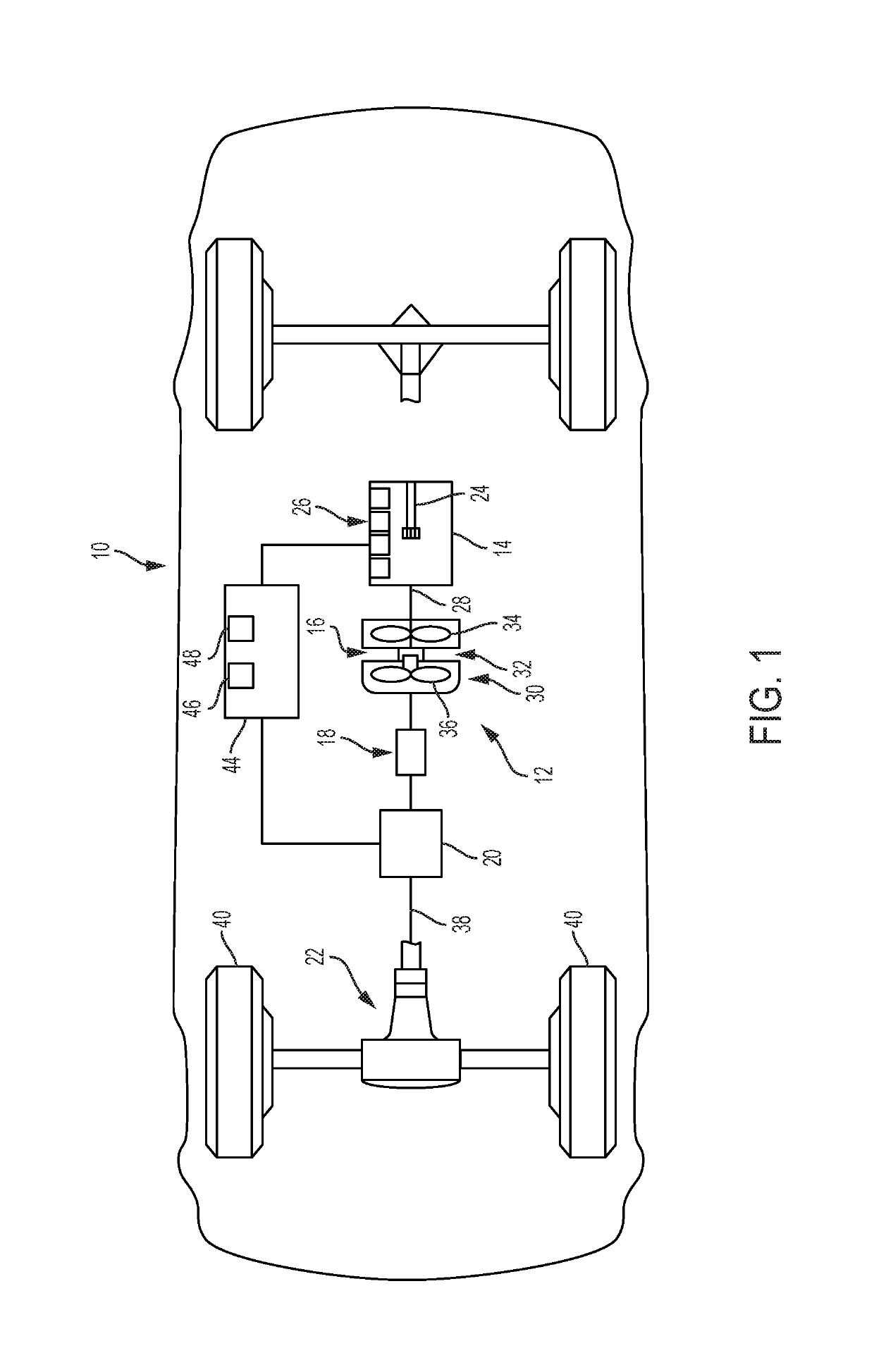
[0028]Reference will now be made in detail to several examples of the disclosure that are illustrated in accompanying drawings. Whenever possible, the same or similar reference numerals are used in the drawings and the description to refer to the same or like parts or steps. The drawings are in simplified form and are not to precise scale. For purposes of convenience and clarity only, directional terms such as top, bottom, left, right, up, over, above, below, beneath, rear, and front, may be used with respect to the drawings. These and similar to directional terms are not to be construed to limit the scope of the disclosure in any manner.

[0029]Referring now to the drawings, wherein like reference numbers correspond to like or similar components throughout the several figures, FIG. 1 schematically illustrates a motor vehicle generally designated at 10. The motor vehicle 10 may be any type of vehicle, such as a car, truck, van, sport-utility vehicle, etc.

[0030]The motor vehicle 10 inc...


PUM


Abstract

A vehicle propulsion system that includes a prime mover having an output shaft, a torque converter including a compressor coupled to the output shaft of the prime mover, a turbine fluidly coupled to the compressor, and a torque converter clutch for selectively mechanically coupling the compressor to the turbine, a continuously variable transmission (CVT) coupled to the turbine of the torque converter, and a controller that is programmed to receive signals indicating operating conditions of the vehicle propulsion system, determine whether the received signals indicate a reduction in ratio in the CVT is impending, determine whether to open the torque converter clutch based upon a determination that a reduction in ratio is impending, and open the torque converter clutch in response to a determination to open the torque converter clutch.

Description

FIELD[0001]The present disclosure relates to a method and system for controlling a vehicle propulsion system.INTRODUCTION[0002]This introduction generally presents the context of the disclosure. Work of the presently named inventors, to the extent it is described in this introduction, as well as aspects of the description that may not otherwise qualify as prior art at the time of filing, are neither expressly nor impliedly admitted as prior art against this disclosure.[0003]A continuously variable transmission (CVT) is a type of vehicle transmission that is capable of continuously changing an output / input speed ratio over a range between a minimum (underdrive) ratio and a maximum (overdrive) ratio, thus permitting an infinitely variable selection of engine operation that can achieve a preferred balance of fuel consumption and engine performance in response to an output torque request. Unlike conventionally-geared transmissions that use one or more planetary gear sets and multiple ro...

Claims


Application Information

Patent Timeline
Patent Type & Authority Patents(United States)
IPC IPC(8): F16H61/14F16H63/46F16D48/06F16H59/62F16H61/662F16H59/70
CPCF16H61/66259F16H59/62F16H61/143F16D48/06F16H63/46F16H2059/702F16D2500/3067F16D2500/3121F16D2500/10412F16D2500/3065F16D2500/3144F16D2500/308F16H2059/704B60W10/02B60W10/06B60W10/101B60W30/18072B60W2510/0638B60W2540/10F16D2500/10487F16D2500/30806F16D2500/70424
Inventor ABINGTON, JAMESRENQUIST, JACOB V.
Owner GM GLOBAL TECH OPERATIONS LLC
Why Eureka
Try Eureka