Optical image capturing system

a technology of optical image and optical image, applied in the field of optical image capture system, can solve the problems of occupying a significant amount of space, affecting the design and manufacture of miniaturized surveillance cameras in the future, and high cost of icr elements, so as to improve the total pixels contained in images and imaging quality, increase the amount of incoming light, and widen the view angle of the optical image capturing system

Active Publication Date: 2019-10-01
ABILITY OPTO ELECTRONICS TECH
View PDF11 Cites 2 Cited by
  • Summary
  • Abstract
  • Description
  • Claims
  • Application Information

AI Technical Summary

Benefits of technology

[0005]The aspect of embodiment of the present disclosure directs to an optical image capturing system and an optical image capturing lens which use combination of refractive powers, convex and concave surfaces of three-piece optical lenses (the convex or concave surface in the disclosure denotes the geometrical shape of an image-side surface or an object-side surface of each lens on an optical axis) to increase the amount of incoming light of the optical image capturing system, widen the view angle of the optical image capturing system, and to improve the total pixels contained in an image and the imaging quality, so as to be applied to minimized electronic products.
[0006]In addition, when it comes to certain application of optical imaging, there will be a need to capture image via light sources with wavelengths in both visible and infrared ranges, an example of this kind of application is IP video surveillance camera, which is equipped with the Day & Night function. The visible spectrum for human vision has wavelengths ranging from 400 to 700 nm, but the image formed on the camera sensor includes infrared light, which is invisible to human eyes. Therefore, under certain circumstances, an IR cut filter removable (ICR) is placed before the sensor of the IP video surveillance camera, in order to ensure that only the light that is visible to human eyes is picked up by the sensor eventually, so as to enhance the “fidelity” of the image. The ICR of the IP video surveillance camera can completely filter out the infrared light under daytime mode to avoid color cast; whereas under night mode, it allows infrared light to pass through the lens to enhance the image brightness. Nevertheless, the elements of the ICR occupy a significant amount of space and are expensive, which impede to the design and manufacture of miniaturized surveillance cameras in the future.
[0007]The aspect of embodiment of the present disclosure directs to an optical image capturing system and an optical image capturing lens which utilize the combination of refractive powers, convex surfaces and concave surfaces of four lenses, as well as the selection of materials thereof, to reduce the difference between the imaging focal length of visible light and imaging focal length of infrared light, in order to achieve the near “confocal” effect without the use of ICR elements.

Problems solved by technology

Nevertheless, the elements of the ICR occupy a significant amount of space and are expensive, which impede to the design and manufacture of miniaturized surveillance cameras in the future.

Method used


Image

  • Optical image capturing system
  • Optical image capturing system
  • Optical image capturing system

Examples


first embodiment

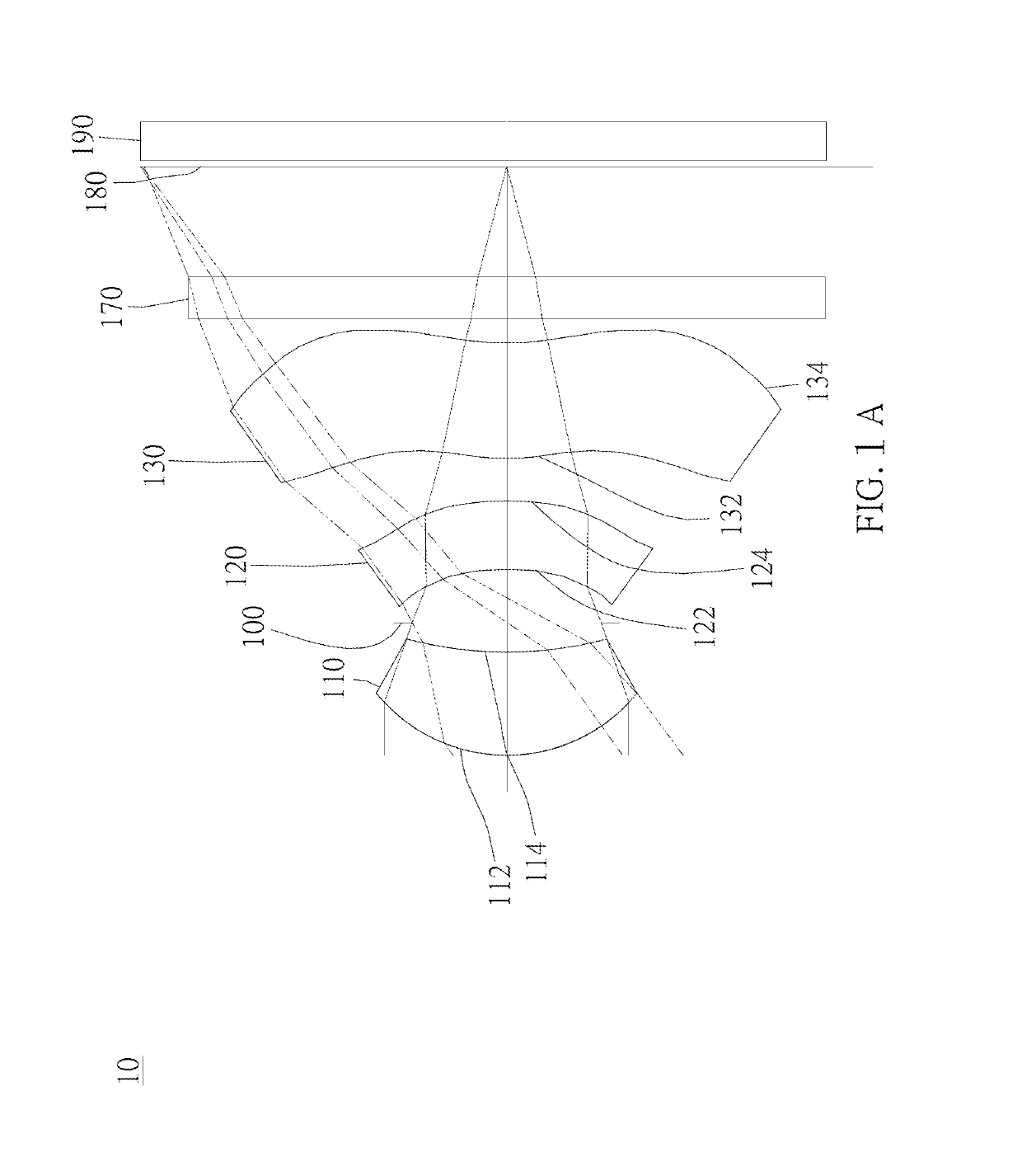
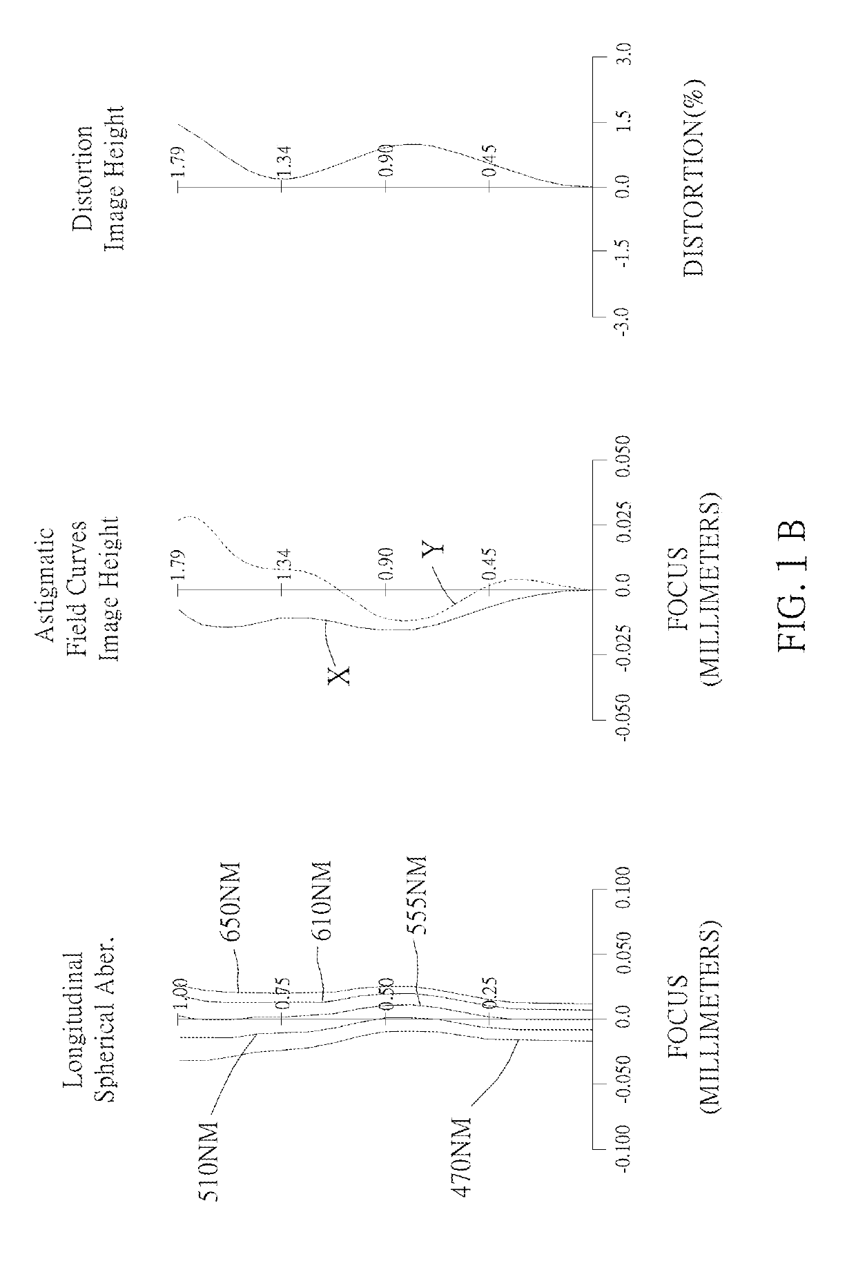
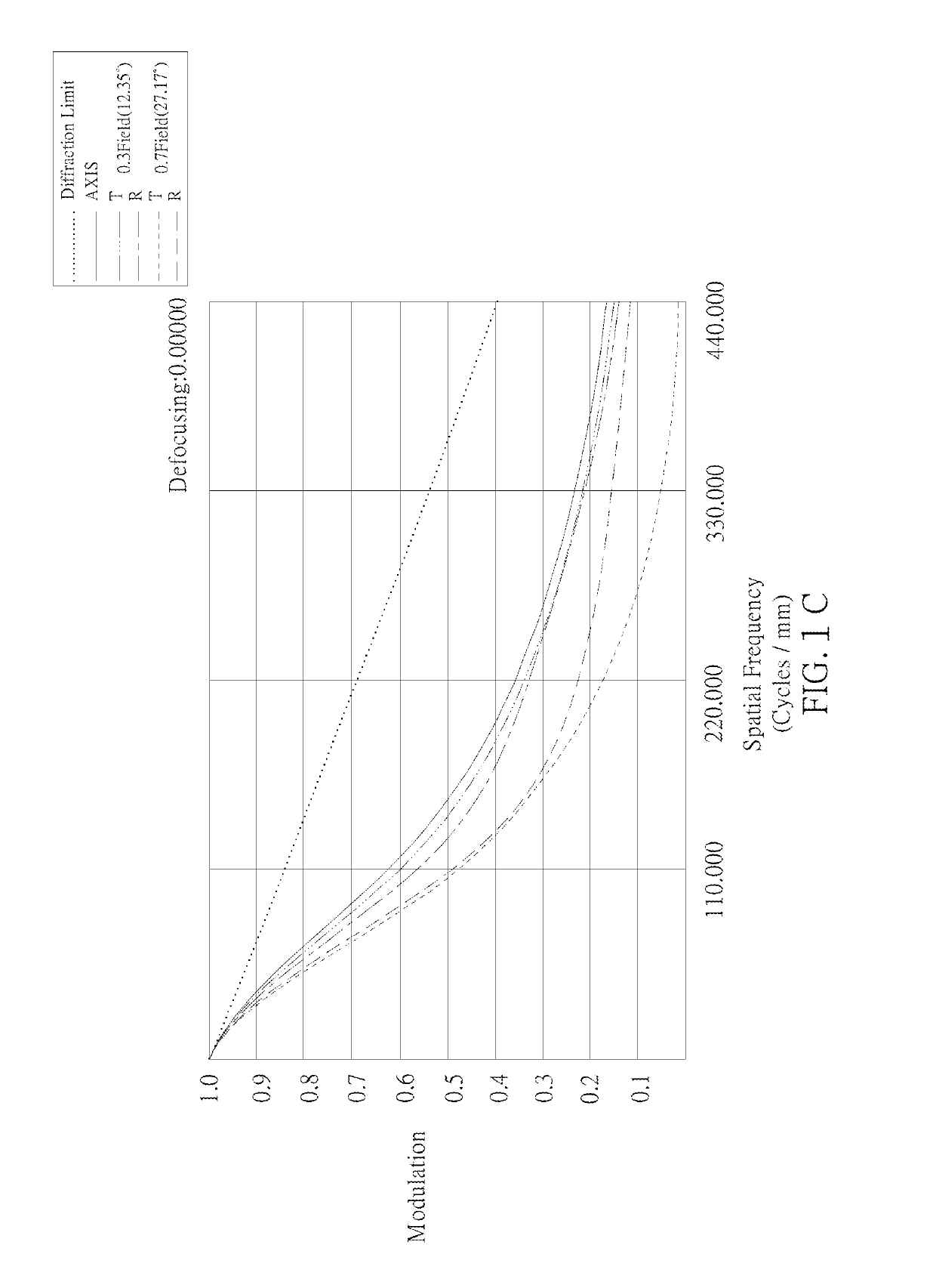
[0125]As shown in FIG. 1A and FIG. 1B, an optical image capturing system 10 of the first embodiment of the present invention includes, along an optical axis from an object side to an image side, a first lens 110, an aperture 100, a second lens 120, a third lens 130, an infrared rays filter 170, an image plane 180, and an image sensor 190. FIG. 1C shows a modulation transformation of the optical image capturing system 10 of the first embodiment of the present application. FIG. 1D is a diagram showing the through-focus MTF values of the visible light spectrum at the central field of view, 0.3 field of view, and 0.7 field of view of the first embodiment of the present invention. FIG. 1E is a diagram showing the through-focus MTF values of the infrared light spectrum at the central field of view, 0.3 field of view, and 0.7 field of view of the first embodiment of the present disclosure.

[0126]The first lens 110 has positive refractive power and is made of plastic. An object-side surface ...

second embodiment

[0168]As shown in FIG. 2A and FIG. 2B, an optical image capturing system 20 of the second embodiment of the present invention includes, along an optical axis from an object side to an image side, an aperture 200, a first lens 210, a second lens 220, a third lens 230, an infrared rays filter 270, an image plane 280, and an image sensor 290. FIG. 2C shows a modulation transformation of the optical image capturing system 20 of the second embodiment of the present application. FIG. 2D is a diagram showing the through-focus MTF values of the visible light spectrum at the central field of view, 0.3 field of view, and 0.7 field of view of the second embodiment of the present invention. FIG. 2E is a diagram showing the through-focus MTF values of the infrared light spectrum at the central field of view, 0.3 field of view, and 0.7 field of view of the second embodiment of the present disclosure.

[0169]The first lens 210 has positive refractive power and is made of plastic. An object-side surf...

third embodiment

[0181]As shown in FIG. 3A and FIG. 3B, an optical image capturing system of the third embodiment of the present invention includes, along an optical axis from an object side to an image side, an aperture 300, a first lens 310, a second lens 320, a third lens 330, an infrared rays filter 370, an image plane 380, and an image sensor 390. FIG. 3C shows a modulation transformation of the optical image capturing system 30 of the third embodiment of the present application. FIG. 3D is a diagram showing the through-focus MTF values of the visible light spectrum at the central field of view, 0.3 field of view, and 0.7 field of view of the third embodiment of the present invention. FIG. 3E is a diagram showing the through-focus MTF values of the infrared light spectrum at the central field of view, 0.3 field of view, and 0.7 field of view of the third embodiment of the present disclosure.

[0182]The first lens 310 has positive refractive power and is made of plastic. An object-side surface 312...


PUM


Abstract

The invention discloses a three-piece optical lens for capturing image and a three-piece optical module for capturing image. In order from an object side to an image side, the optical lens along the optical axis comprises a first lens with positive refractive power; a second lens with refractive power; and a third lens with refractive power; and at least one of the image-side surface and object-side surface of each of the three lenses are aspheric. The optical lens can increase aperture value and improve the imaging quality for use in compact cameras.

Description

BACKGROUND OF THE INVENTION1. Technical Field[0001]The present invention relates generally to an optical system, and more particularly to a compact optical image capturing system for an electronic device.2. Description of Related Art[0002]In recent years, with the rise of portable electronic devices having camera functionalities, the demand for an optical image capturing system is raised gradually. The image sensing device of the ordinary photographing camera is commonly selected from charge coupled device (CCD) or complementary metal-oxide semiconductor sensor (CMOS Sensor). In addition, as advanced semiconductor manufacturing technology enables the minimization of the pixel size of the image sensing device, the development of the optical image capturing system towards the field of high pixels. Therefore, the requirement for high imaging quality is rapidly raised.[0003]The conventional optical system of the portable electronic device usually has two lenses. However, the optical sys...

Claims


Application Information

Patent Timeline
Patent Type & Authority Patents(United States)
IPC IPC(8): G02B13/00G02B9/14
CPCG02B13/0035G02B9/14G02B13/008G02B13/18
Inventor LAI, CHIEN-HSUNLIAO, KUO-YULIU, YAO-WEICHANG, YEONG-MING
Owner ABILITY OPTO ELECTRONICS TECH
Why Eureka
Try Eureka