
Seal bar and heat sealing apparatus

a technology of sealing bar and heat sealing apparatus, which is applied in the direction of heat measurement, instruments, transportation and packaging, etc., can solve the problem of not being able to properly control the temperature of the sealing surface, and achieve the effect of easy response to the actual temperature, accurate detection of temperature changes, and high accuracy

Active Publication Date: 2019-10-15
ORMON CORP
View PDF13 Cites 0 Cited by
  • Summary
  • Abstract
  • Description
  • Claims
  • Application Information

AI Technical Summary

Benefits of technology

The present invention is about a technique for accurately detecting the temperature of a sealing surface that is not affected by sealing conditions. A seal bar is used to transfer heat from a heater to the sealing surface and a temperature sensor is placed around the sealing surface to detect the temperature. This allows for easy detection of changes in temperature on the sealing surface without being affected by the sealing conditions. The heat sealing apparatus controls the heater based on the detected temperature, which enables accurate control of the sealing surface temperature. Overall, the invention enables accurate detection of the temperature of a sealing surface.

Problems solved by technology

Therefore, by simply setting an offset value and then correcting the temperature detected by the temperature sensor, it is impossible to properly control the temperature of the sealing surface.

Method used


Image

  • Seal bar and heat sealing apparatus
  • Seal bar and heat sealing apparatus
  • Seal bar and heat sealing apparatus

Examples


first embodiment

[1] First Embodiment

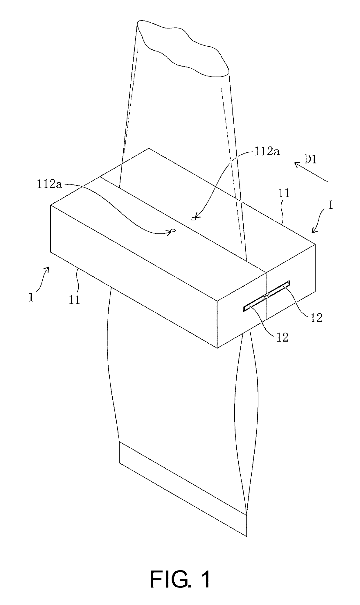
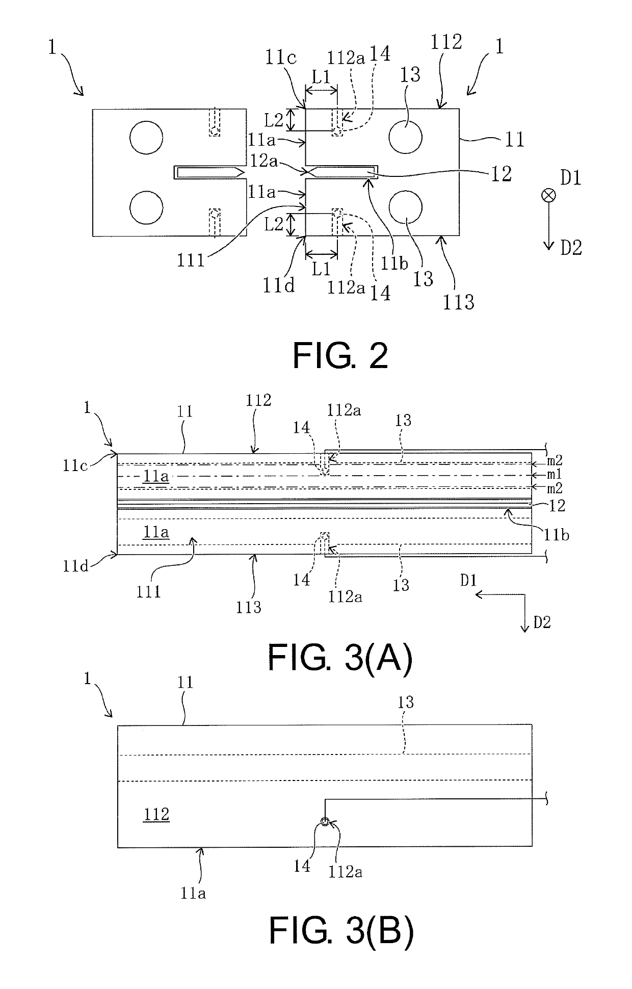
[0023]FIGS. 1 and 2 are respectively a perspective view and a side view conceptually illustrating a heat sealing apparatus according to a first embodiment. As illustrated in FIGS. 1 and 2, the heat sealing apparatus has a pair of seal bars 1 which are disposed to face each other, and a sealing surface 11a is formed on each facing surface 111. Additionally, the pair of seal bars 1 press a packaging material passing through between the pair of seal bars 1 in a heated state to thermally compress the packaging material and thus form a package such as a snack bag or the like. Further, in FIG. 2, the pair of seal bars 1 are symmetrical, and only the seal bar 1 on a right side is designated by a reference numeral.

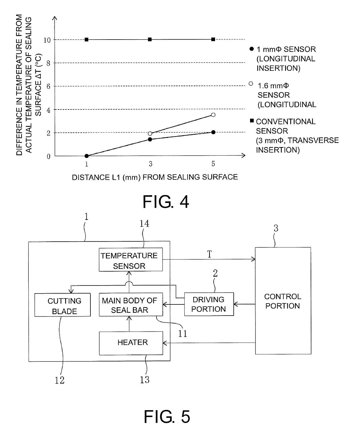
[0024]Specifically, each of the seal bars 1 includes a rod-shaped main body 11 having a sealing surface 11a, a cutting blade 12 used for cutting the packaging material at a thermocompression bonding portion, a heater 13 and a temperature sensor 14.

[0025]The cut...

second embodiment

[2] Second Embodiment

[0043]FIG. 6 is a side view conceptually illustrating the heat sealing apparatus according to a second embodiment. As illustrated in FIG. 6, in each seal bar 1, the upper end surface 112 and the lower end surface 113 may be formed to be inclined with respect to the sealing surface 11a (facing surface 111). In this case, the perforation 112a may be provided on each of the inclined upper end surface 112 and lower end surface 113, and the distance L2 is a distance from an opening position of the perforation 112a in each of the upper end surface 112 and the lower end surface 113 in the direction D2.

[3] Other Embodiments

[0044]In the above-described heat sealing apparatus, the present invention is not limited to the case in which the temperature sensor 14 is provided individually to correspond to each of the upper sealing surface 11a and the lower sealing surface 11a, and only one temperature sensor 14 may be provided to correspond to only one of the sealing surfaces ...


PUM

PropertyMeasurementUnit
distanceaaaaaaaaaa
diameteraaaaaaaaaa
diameteraaaaaaaaaa

Abstract

A technique for accurately detecting a temperature of a sealing surface which is not affected by sealing conditions or the like is provided. A seal bar (1) is a rod-shaped seal bar having a sealing surface (11a) and includes a heater (13) and a temperature sensor (14). The heater (13) is provided in a main body of the seal bar (1) and extends in an extending direction (D1) of the main body (11). The temperature sensor (14) is provided at a position between the sealing surface (11a) and the heater (13) in the main body (11) of the seal bar (1) and is inserted into the main body (11) of the seal bar (1) from an end surface (upper end surface (112) or the like) which intersects a long side of the sealing surface (11a).

Description

CROSS-REFERENCE TO RELATED APPLICATION[0001]This application claims the priority benefit of Japanese application serial no. 2016-249126, filed on Dec. 22, 2016. The entirety of the above-mentioned patent application is hereby incorporated by reference herein and made a part of this specification.BACKGROUND OF THE INVENTIONField of the Invention[0002]The invention relates to a technique for sealing a packaging material or the like.Description of Related Art[0003]For example, in a packaging machine, a seal bar having a sealing surface for thermocompression bonding is used for thermocompression bonding (sealing) of a packaging material when a package such as a snack bag is formed. In order to obtain a satisfactory sealing state at a thermocompression bonding portion of the packaging material, it is preferable to directly detect and control a temperature of the sealing surface with a temperature sensor. However, when the temperature sensor is provided on the sealing surface for this pur...

Claims


Application Information

Patent Timeline
Patent Type & Authority Patents(United States)
IPC IPC(8): B29C65/24B29C65/30B29C65/18B29C51/10B29C65/74B29C65/00B29C65/10B65B51/10
CPCB65B51/10B65B2051/105B29C65/18B29C65/305B29C65/745B29C66/1122B29C66/4312B29C66/849B29C66/91212B29C66/91231B29C66/91213G01K1/14G05D23/30B29C65/242B29C51/10B29C65/103B29C66/431
Inventor OGAWA, HIRONORIUEDA, NORIHIROTARUMOTO, YUKIYAMADA, TAKAAKIOZAKI, MASAHIROOHTA, MORIHISATAKAISHI, AKIRATOGAWA, HIROYUKIMUKAI, ATSUSHI
Owner ORMON CORP
Learn More